Project 1
Overview
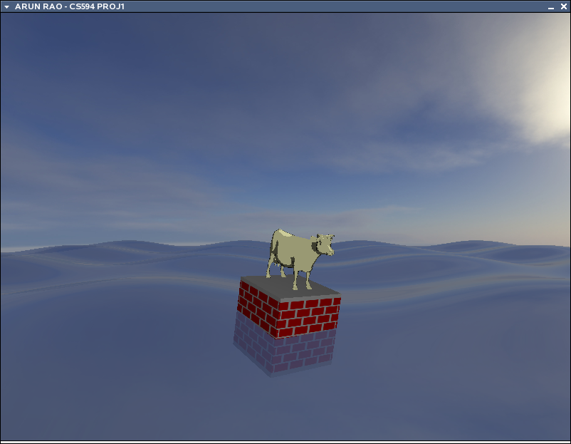
I will be discussing my implementation of project 1. On top of
the requirements for the project, I have incorporated a different
complex model, waves of slightly transparent water and use of cubemap
reflection. The end result looks like the following image.
I will start
off by discussing my implementation of the Brick Shader applied to the
cube, followed by the Toon Shader applied to the cow. Then I will
discuss my implementation of the waves and how the shader for that
affected the previous two shaders.
Brick Shader v1.0
The goal of the brick shader is to perform procedural texturing of a
cube. Given the right parameters to also have the bricks perform
a wrap around the cube, laterally, and to ignore the top and bottom by
placing mortar. After all that, we had to perform some kind of
smoothing to help antialias the bricks.
My brick shader is a bit complicated, and after discussing with other
students very much sub-optimal, but it works. I've also added a
cheat into the shader so that even if the parameters for brick size and
brick percentage do not really allow the brick to nicely wrap around
the edges of the cube, the bricks at the edge will no matter how bad it
may look. Taking the original vertex shader I changed MCposition
to be a vec3 so that I can pass a z-value to the fragment shader.
I also send the gl_Normal of the vertex in model coordinate space to
the fragment shader. The result is the following vertex shader:
uniform vec3
LightPosition;

const float
SpecularContribution = 0.3;
const float DiffuseContribution  = 1.0 - SpecularContribution;

varying float LightIntensity;
varying vec3  MCposition;
varying vec3  normal;

void main(void)
{
   vec3 ecPosition = vec3 (gl_ModelViewMatrix * gl_Vertex);
   vec3 tnorm      = normalize(gl_NormalMatrix * gl_Normal);
   vec3 lightVec   = normalize(LightPosition - ecPosition);

   vec3 reflectVec = reflect(-lightVec, tnorm);
   vec3 viewVec    = normalize(-ecPosition);
   float diffuse   = max(dot(lightVec, tnorm), 0.0);
   float spec      = 0.0;

   if (diffuse > 0.0)
   {
      spec = max(dot(reflectVec, viewVec), 0.0);
      spec = pow(spec, 16.0);
   }

   LightIntensity  = DiffuseContribution * diffuse + SpecularContribution * spec;

   MCposition      = gl_Vertex.xyz;
   normal          = normalize(gl_Normal);
   gl_Position     = ftransform();
}
The fragment shader is where we do our procedural texture. Here
we determine if our fragment is in the top or bottom most row of our
cube. If either of those are the case we force the color to be
mortar, otherwise we run our brick algorithm. After we get our
texture color, we apply the LightIntensity from the vertex shader to
apply our diffuse and specular lighting. We recieve our
parameters for the brick texture here. I also take into account
the size of the object i'm working with. I assume I'm working
with a cube and that helps determine how to modify the brick shader
(i.e. shift the values laterally) based on the normal of the
surface. This shader will probably only work well with a cube,
and is definitely not the right way to do things in general, but
whatever. The key thing for making the brick shader work is that
we use the z-value of the MCposition in place of the x-value when we
have a face with a normal in the +x or -x direction. Otherwise we
will not have any means of alternating the colors. That knowledge
in combination with each row alternating the shifting of the bricks, we
can perform an alternation of that alternating action too.
Meaning, if a row of bricks is shifted on one face, then the
adjacent/perpendicular faces will not shift the bricks of the same row,
and vice versa.
uniform vec3    BrickColor, MortarColor;
uniform vec2    BrickSize;
uniform vec2    BrickPct;
uniform float   ObjScale;
varying vec3    MCposition;
varying float   LightIntensity;
varying vec3    normal;
float           BricksInRow;
float           shiftx = 0.0;

//-----------------------------------------------------------------
void brick_func(vec2 p, vec3 sp, out vec3 color);

//-----------------------------------------------------------------
void main(void)
{
    vec2 position;
    vec3 smcpos;
    vec3 color;
    smcpos = MCposition * ObjScale; 	// scaled MCposition
    position = smcpos.xy / BrickSize;	// our position within real space
    float bic = ObjScale / BrickSize.y;	// bricks in col = # of rows

    // top and bottom row are mortar
    if( abs(smcpos.y) / BrickSize.y > floor(bic))
        color = MortarColor;
    else
        brick_func(position,smcpos,color);

    color *= LightIntensity;
    gl_FragColor = vec4( color, 1.0);
}

//-----------------------------------------------------------------
void brick_func(vec2 p, vec3 sp,out vec3 color)
{
    vec2 useBrick;
    BricksInRow = ObjScale / BrickSize.x;

    // bir = integer value of BricksInRow
    float bir = floor(BricksInRow);
    // mortar percentage, used for smoothstep and shifting
    vec2 mpct = vec2(1.0,1.0) - BrickPct;
    float fbir = fract(BricksInRow);

    // modify bir if we have an even division or more than half left over
    if( fbir == 0.0 )
        bir -= 1.0;
    else if( fbir > .5 )
        bir += 1.0;

    // each row alternates which is in center (brick or mortar )
    // and each face alternates that alternation!

    if( normal.x == 0.0 ) // front and back faces
    {
        if( fract(p.y * 0.5 ) > 0.5 ) // brick centered
            shiftx = .5 * BrickPct.x;
    }
    else if( normal.z == 0.0 ) // side faces
    {
        // use z coordinates instead
        p.x = sp.z / BrickSize.x;
        sp.x = sp.z;

        if( fract(p.y * 0.5 ) < 0.5 ) // brick centered
            shiftx = .5 * BrickPct.x;
    }
    p.x += shiftx;

    // shift so brick color gets centered
    p -= -0.5 * mpct;
    p = fract(p);
    p = abs( p - vec2(.5, mpct.y));

    // little cheat !!!!!!! forces spaces on edge to be brick
    if( (abs(sp.x) / BrickSize.x) > bir)
    {
        p.x = 1.0;
    }

    useBrick = smoothstep(mpct * .5, mpct, p);
    color = mix(MortarColor, BrickColor, useBrick.x * useBrick.y);
}
So if you notice, when our normal.x == 0 then we know we are drawing on
the front or back face and so we check if we are on an even or odd
brick and sift as necessary. When we are on a side face (i.e.
normal.z == 0) then we switch our comparison operator from > to
<, effectively switching the alternation. Then we shift our
position in the brick by half of the mortar percentage to try and
center our position. Then we determine the position of our point
from the center of our brick and here is where we can force the edges
on the face to be brick based on how determined how many bricks should
span across this row. This little override can cause some nasty
visuals though, if the brick parameters aren't right... but hey... at
least the bricks will ALWAYS reach the corner.
Toon Shader v1.0
The toon shader is really easy to do. All we need to do is find
out what our real normal is in world space, rather then model space in
our vertex shader, pass that data to the fragment and do our intensity
thresholding in the fragment shader.
So our vertex shader looks like the following:
varying vec3    normal;

void main(void)
{
    normal = normalize( gl_NormalMatrix * gl_Normal );
    gl_Position = ftransform();
}
And we follow up with our fragment shader.
varying vec3 normal;

void main(void)
{
    vec4 color;
    float intensity;
    vec3 n = normal;
    n = normalize(n);
    intensity = dot(vec3(normalize(gl_LightSource[1].position)),n);

    if( intensity > 0.94 )
        color = vec4( 1, 1, 1, 1);
    else if( intensity > .5 )
        color = vec4( .75, .75, .75, 1);
    else if( intensity > .2 )
        color = vec4( .3, .3, .3, 1);
    else
        color = vec4( 0, 0, 0, 1);

    color = color * gl_FrontMaterial.diffuse;

    gl_FragColor = color;

}
The one big difference right now is that I incorporated the diffuse
color with the color derived from intensity by blending. So we
end up geting not just pure white for the highly specular part of our
object, but a specular yellow, or blue or whatever the diffuse material
color is. So I'm doing a normalize on the light position
per-fragment and I realize that it's actually a waste of computation
and should be something done at worst per-vertex and passed as a
varying to the fragment shader. I didn't care really and I feel
like the performance hit wasn't going to be all that bad... and really
it isn't all that bad.
Wave Shader
So here is where things get interesting. I want to have cool
looking waves, that will eventually displace the objects on it, give a
reflection and be partially see through in order to give the appearence
of water. So how are the waves going to be made? I decided
by just using a simple sum of sines approach. So in the final
version I have two waves in the x-direction and one wave in the
z-direction, all affecting the height of a mesh at a given vertex
position on the xz-plane. The use of two directions is to make
the wave surface be a little more complicated. The nice thing
about using the sum of sines approach is that we can pretty easily
determine the normal of the surface. All we have to do is:
- get the partial derivative in the +x & +z direction
- find the slope of the surface in +x & +z using our derivatives
- take the cross product of the two slopes
- normalize the cross product
So easy! Then we just continue on doing our normal stuff.
We can add some parameters to modify the wavelength, magnitude and use
a uniform time variable to uniformally shift the wave to give us some
animation. In the end, our vertex shader for the wave is as follows
uniform float   Time;

const float     xdiv = 10.0;
const float     zdiv = 8.0;
const float     magx = 1.6;
const float     magz = 1.0;

varying vec3 normal, lightDir, halfVector, eyeDir;
varying vec4 diffuse, ambient;

void main(void)
{
    float h1, h2;
    vec3 v1, v2;

    // determine current position
    h1 = sin((gl_Vertex.z / zdiv) + Time) * magz;
    h2 = sin((gl_Vertex.x / xdiv) + (Time)) * magx +
         sin((gl_Vertex.x / 5) + (Time - 4));
    h1 = h1 + h2;

    gl_Position = gl_ModelViewProjectionMatrix *
        vec4(gl_Vertex.x, gl_Vertex.y + h1, gl_Vertex.z,1);

    // get our two slopes in xy and zy
    // d( sin(u) ) = cos(u)d(u)
    v1 = vec3(  0.0,
                cos((gl_Vertex.z / zdiv) + Time) * magz / zdiv,
                1.0);
    v2 = vec3(  1.0,
                cos((gl_Vertex.x / xdiv) + Time) * magx / xdiv +
                cos((gl_Vertex.x / 5.0) + (Time - 4.0)) / 5.0,
                0.0);

    // find our normal
    // we need derivatives of pos and pos2
    normal = normalize(cross(v1,v2));

    eyeDir = vec3( gl_ModelViewMatrix * gl_Vertex);
    normal = normalize(gl_NormalMatrix * normal);
    lightDir = normalize(vec3(gl_LightSource[1].position));
    halfVector = normalize(gl_LightSource[1].halfVector.xyz);

    diffuse = gl_FrontMaterial.diffuse * gl_LightSource[1].diffuse;
    ambient = gl_FrontMaterial.ambient * gl_LightSource[1].ambient;
    ambient += gl_LightModel.ambient * gl_FrontMaterial.ambient;

}
Cool. Given we setup our alpha-blending & our draw order
properly, we can make our waves look like watery waves in our fragment
shader. We can also provide some reflection just for added effect
using a cube map, and pass the texture unit for the cube map as our
uniform samplerCube variable. The fragment shader is pretty
simple and incorporates the directional lighting that you can find at lighthouse3d.
uniform samplerCube     CubeMapTex;

varying vec3 normal, lightDir, halfVector, eyeDir;
varying vec4 diffuse,ambient;

void main(void)
{
    float NdotL, NdotHV;
    vec4 color = ambient;
    vec3 n = normalize(normal);
    NdotL = max(dot(n,lightDir),0.0);
    if( NdotL > 0.0 )
    {
        color += diffuse * NdotL;
        NdotHV = max( dot( n, normalize(halfVector)), 0.0);
        color += gl_FrontMaterial.specular * gl_LightSource[1].specular *
            pow(NdotHV, gl_FrontMaterial.shininess);

    }

    // our cube map forces us to make the reflectDir negative...
    // mainly cause of our texture resources.... anyway :)
    vec3 reflectDir = -reflect( eyeDir, normal);
    vec4 texturecolor = textureCube( CubeMapTex, normalize(reflectDir));

    gl_FragColor = vec4( vec3(mix( color, texturecolor, .6)) , .8);
}
All this cool wave stuff has to now be incorporated into our vertex
shaders for our brick and toon objects. There are possibilities
for problems though because if we perform our rotation, translation
outside the shader then our sense of direction could get messed
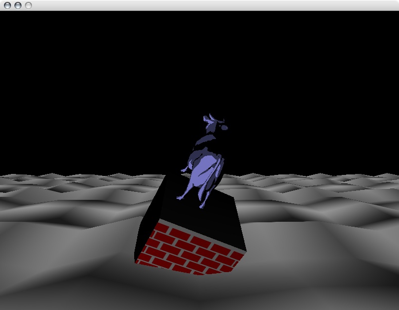
up. Just to give you an idea, look at the picture below.
See how the shading is not consistent? Also, I should note that
the waves are messed up because they were work in progress, but the
order of transformations being important seemed very appearent here.
How do we fix this? Well we do the transformation in the shader
as our dirty hack. Sound fun? Well it is if you are a
twisted person, hell bent on making this work and re-learning some
linear algebra. Sounds like my cup of tea. Let's get
started on our brick shader.
Brick Shader & Toon Shader
Modifications
So we have to add our wave displacement into the brick shader. We
could do this by making a function. But what else do we have to
do? Well we'll make an assumption that we are going to work with
one point when performing the displacement and the orientation based on
the surface normal. This way we can easily determine our xz-plane
transformation and add our y-position based on the wave function.
Then we can apply this to all the vertices of our object so that way we
won't distort our object. After positioning and orienting based
on our wave, we can perform the mandatory spin about our RELATIVE
y-axis. All this means that we'll have to modify our ModelView
matrix, which means that we'll also have to rebuild the Normal matrix
so we can perform the correct lighting calculations. And we'll
have to do it all in the shader. See why this is fun? :)
Now our wave function looks similar to our wave vertex shader, except
we will be creating a basis matrix for our orientation of our object,
and we will replace the use of gl_Vertex with our fixed position, which
I will call testPosition. Here's what it looks like
vec3 testPosition = vec3( 0.0, 0.0, -10 );
mat4 wave_rot_mat;
...
void wave_func( inout vec3 tp, inout vec3 tn)
{
	vec3 v1, v2, pos1, pos2;
	float h1, h2;
	// determine current height displacement
	h1 = sin((testPosition.z / zdiv) + Time) * magz;
	h2 = sin( (testPosition.x / xdiv) + Time) * magx +
             sin( (testPosition.x / 5.0 ) + (Time - 4.0));
	tp = vec3( 0.0, h1 + h2, 0.0); // only take y component
	// get our two slopes in xy and zy
	// d/dx( sin(u) ) = cos(u)d/dx(u)
	// v1 with respect to z
	// v2 with respect to x
	v1 = vec3(  0.0,
                    cos((testPosition.z / zdiv) + Time) * magz / zdiv,
                    1.0);
    	v2 = vec3(  1.0,
                    cos((testPosition.x / xdiv) + Time) * magx / xdiv +
                    cos( (testPosition.x / 5.0 ) + (Time - 4)) / 5.0,
                    0.0);

	// find our normal, should be in positive y direction
	v1 = normalize(v1);
	v2 = normalize(v2);
	tn = normalize(cross(v1,v2));
	// should have our basis vectors!! v1, v2, tn... now build a matrix
	wave_rot_mat = identity;
	wave_rot_mat[0] = vec4( v2, 0.0);
	wave_rot_mat[1] = vec4( tn, 0.0);
	wave_rot_mat[2] = vec4( v1, 0.0);
}
Now that we've got that, we just apply the transformations to a copy of
our ModelView matrix, and we make a call to a function that will
rebuild our normal matrix. The shader addition looks like this:
uniform float Spin;
...
void main(void) {
	vec3 tp = vec3(0.0,0.0,0.0);
	vec3 tn = vec3(0.0,0.0,0.0);
	mat4 mvmat = gl_ModelViewMatrix;
	mat3 nmat = gl_NormalMatrix;

	// apply wave displacement
	wave_func(tp,tn);

	// translation
	mat4 tempmat = identity;
	tempmat[3][0] = testPosition.x;
	tempmat[3][1] = tp.y;
	tempmat[3][2] = testPosition.z;
	mvmat *= tempmat;

	// apply rotation due to normal at wave
	mvmat *= wave_rot_mat;

	mat3 nmat = gl_NormalMatrix; // just in case

	// apply rotation about y-axis
	tempmat = identity;
	tempmat[0][0] = cos(Spin);
	tempmat[2][0] = sin(Spin);
	tempmat[0][2] = -sin(Spin);
	tempmat[2][2] = cos(Spin);
	tempmat[3][1] = CubeScale;
	mvmat *= tempmat;

	// rebuild normal matrix
	build_norm_mat(mvmat,nmat);

	// let's reuse tp
	tp = gl_Vertex.xyz;
	normal = normalize( nmat * gl_Normal );
	gl_Position = gl_ProjectionMatrix * mvmat * vec4(tp,1);
	... // continue on with rest of normal shader stuff
Now you should know that referencing a matrix in GLSL is the same as in
OpenGL, it's [column][row] & not the traditional
[row][column]. So how are we going to rebuild our normal
matrix? Well if you look at the GLSL "orange" book, you will see
the gl_NormalMatrix is the upper-left 3x3 of the ModelView matrix,
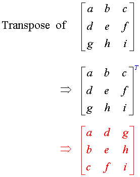
inverted and then transposed. In case you don't remember how to
do a 3x3 inversion or a 3x3 transpose, this should clear things up.
So the cool thing is we can do this all at once. Now I think we
can get away with not doing the transpose since it's an orthogonal
matrix. So this is the function that does it.
//-----------------------------------------------------------------
float determinant(mat3 m)
{
    float t = 0.0;
    t = m[0][0] * ((m[1][1] * m[2][2]) - (m[2][1] * m[1][2]));
    t+= m[0][1] * ((m[1][2] * m[2][0]) - (m[2][2] * m[1][0]));
    t+= m[0][2] * ((m[1][0] * m[2][1]) - (m[2][0] * m[1][1]));

    return t;
}

float determinant(mat2 m)
{
    return ((m[0][0] * m[1][1]) - (m[1][0] * m[0][1]));
}

//-----------------------------------------------------------------
// normal matrix is transpose of inverse of upper left 3x3 of modelview matrix
void build_norm_mat(void)
{
    mat3  tnmat;
    float d;
    for( int i = 0; i < 3; i++)
        for( int k = 0; k < 3; k++)
            nmat[i][k] = mvmat[i][k];

    d = determinant(nmat);
    // take determinant and transpose at same time
    tnmat[0][0] =
        determinant(mat2(nmat[1][1], nmat[1][2], nmat[2][1], nmat[2][2]));
    tnmat[1][0] =
        determinant(mat2(nmat[0][2], nmat[0][1], nmat[2][2], nmat[2][1]));
    tnmat[2][0] =
        determinant(mat2(nmat[0][1], nmat[0][2], nmat[1][1], nmat[1][2]));
    tnmat[0][1] =
        determinant(mat2(nmat[1][2], nmat[1][0], nmat[2][2], nmat[2][1]));
    tnmat[1][1] =
        determinant(mat2(nmat[0][0], nmat[0][2], nmat[2][1], nmat[2][2]));
    tnmat[2][1] =
        determinant(mat2(nmat[1][2], nmat[0][0], nmat[1][2], nmat[1][0]));
    tnmat[0][2] =
        determinant(mat2(nmat[1][0], nmat[1][1], nmat[2][0], nmat[2][1]));
    tnmat[1][2] =
        determinant(mat2(nmat[0][1], nmat[0][0], nmat[2][1], nmat[2][0]));
    tnmat[2][2] =
        determinant(mat2(nmat[0][0], nmat[0][1], nmat[1][0], nmat[1][1]));

    nmat = tnmat / d;
}
Cool, now that that's all done. Well, we're done. Here is
the
source code, and there is a
README.txt file with directions on how to build, run, manipulate,
control the application. The code should work on Mac OS X, Linux
(32 bit & 64 bit). In order to build the application you will
need the
SDL library. On the
Mac you can use Fink, or install from source. Depending on which
version of Linux you are using, you could probably install SDL via a
package manager (e.g. apt-get, yast2, etc.). For those interested, I have my
presentation from class.
Questions/Comments send mail to Arun Rao