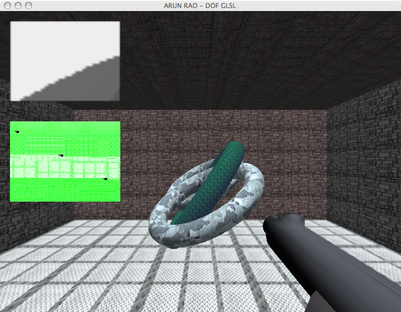
What we have here can be seen as
nothing being written to the second target. In the first picture,
I have gl_FragData[1] being assigned a value last. In the second
I have gl_FragData[0] being assigned a value last. If I comment
out one, the other seems to be writing to the first color
attachment. ALWAYS!!! I have submitted a detailed bug
report to Apple about this. So I decided that I would only work
in Linux and on an NVidia card that was made about the time of the
GeForce 6 or 7 series.
At this point, we need to do one more pass.
Pass Three: Sampling The Color
Map and Applying the Blur
Here I go back to doing the same kind of thing that Riguer, et. al. did
with first technique described in their paper. Using some
randomly created set of vectors as uniforms, I scale the vectors by the
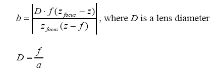
circle of confusion calculation for that fragment. The circle of
confusion is simply calculated by using the blur coefficient from pass
two, in a scale from [0,1], multiplied by the maximum circle of
confusion. I run through the array of vectors and sample the
color map at the determined pixels.
I deal with color bleading by modifying the contribution that a sample
by comparing the depth from focal distance value of the sampled point
with the depth from focal distance value of the sample in the center
(i.e. the texel that would be used if we weren't doing any
blurring). If the distance is greater then I add 1 to the total
weight, otherwise I add the blur coefficient to the total weight.
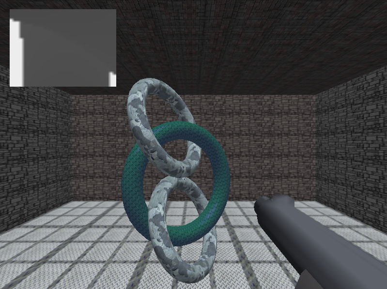
As a result, well... just look at the picture! :)
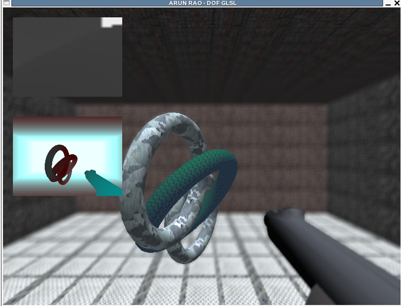
Here we can see that part of the tori
is in focus, the farther part being a little more blurry. As goes
for the floor and celing. We can also see that the back wall is
nice and blurry and we dont' have any major color leaking between the
closest torus and the far wall.
The Extras!!
Head Tracking, Varrier Mode & GeoWall Mode!
I got a hold of Bob's
tracker code
that can access the shared memory to retrieve head tracking data sent
by TrackD, which I believe is feed with data coming from
Javier's
Neural Network based Head Tracking system. That, in
combination with Bob's new
varrier
combiner code, allowed me to port my project as a personal varrier
application! I had to figure out how the varrier combiner worked,
and determined that I had to do some things a little different from
Bob's example code. In the case of creating the left eye and
right eye views, I decided that I needed to add a function to perform
pass three for both eyes, and pass two for both eyes before I called
the code to combine the views using the vc_combine function. I
then determined that I could easily reuse the outputs of new function
and render in geowall mode to a single large framebuffer.
Eye Tracking
After messing around with the eye tracker that is in the lab, I was
able to eventually get the data being sent by the eye tracker to an
outside program. After calibration, the eye tracker system can
output the Point of Reference (POR) over a serial port. The POR
is basically the screen coordinate the user is looking at. I
wrote code to read from the serial port and extract the values.
The big problem was that the eye tracker uses an infrared LED (IR LED)
to help get the image it needs to process and return the desired
information. Now when using the eye tracker alone this is
actually not much of a problem, but the Personal Varrier system tracks
the user's head using a large number of infrared LEDs, which surround
the perimeter of the large 30" Apple Display being used for it.
When looking at the screen, the LEDs used by the head tracker over load
the image, especially if you are wearing glasses that reflect the
incoming infrared light, such as mine :) This basically makes eye
tracking not reliable when the two are put together, at least at this
point.
The other problem with the eye tracker is if you need to scratch your
head and cause the eye tracking unit to move, then you will lose
calibration and your POR values can be very very wrong. This is
because the eye tracking unit is something you wear on your head and
has a piece of material that is used to reflect the light coming off of
the unit's single IR LED. If you move the unit, then the
reflecting material could be pointing to your eye brow or your cheek,
instead of your eyes. This is actually bound to happen as that
unit seems to slide down my face over time when I wear it.
Had this seemed to be a practical setup and was doable then we could
have had some interesting matrix transformations to get the vector the
eye was making into the virtual world, and modify our pass one to
create an off-axis projection to draw the area the user was
looking at. With that information we could really modify the
focal distance based on what the user was looking with their own eyes,
and not what was in the center of the screen. I believe this is
still doable, and maybe something that I will look into over the summer.
Downloading, Building &
Running
You can download the source code here:
dof.tar.gz
To build you need to have SDL setup, as well as libjpeg and libpng
available. Modify src/makefile as needed. The application
will compile on the Mac, but as stated before, it will not run
properly. After making the necessary adjustments just type 'make'
Here are the following usages of the application
Run with default parameters:           ./dof
Run with specified screen dimensions:  ./dof <width> <height>
Run in GeoWall mode:                   ./dof <width> <height> -geowall
NOTE: width is the width for one viewport of the eye
Run in Personal Varrier mode:          ./dof <width> <height> -varrier
NOTE: The width and height parameters for the Personal Varrier in the lab is 2560 x 1600
To move around the standard W,A,S,D control scheme is used, with the
mouse to look around. To increase or decrease the focal range,
use the 'j' and 'l' keys respectively. For adjusting the maximum
circle of confusion use the '[' and ']' keys. One important thing
to note, if you want everything to be sharp, adjust the maximum circle
of confusion to the point where the maximum circle of confusion is
about 0.5. Then the same texel will be sampled repeatedly and
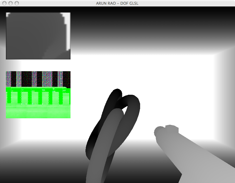
then used. To toggle on/off the views of pass one and two press
the '1' and '2' keys.