|
Realistic Skin Rendering- GPU Shader for Realistic Skin -Nov, 2008Sangyoon Lee (sjames @ evl.uic.edu)Electronic Visualization LaboratoryUniversity of Illinois at Chicago |
During the past few years, there has been many of interesting studies especially in realistic skin rendering in realtime graphics. Most importantly all these advances rely on high performance programmable GPU. In project 3, I will explore and integrate those techinques for realistic human face rendering especially using subsurface scattering (SSS) [1,2,3,4].
(image source: http://graphics.ucsd.edu/papers/layered/)
- Why?
First of all, this topic is well fit to my current research that creates realistic computer generated human so called avatar. Result of this project will benefit my work directly to increase believability of artificial character.
- What to expect?
In short, the expected result is an implementation of SSS for the head model used in project 1. In addition ot this, a few of heuristic approaches will be tested (i.e. reducing the computing time by using fake translucent map instead of approximation in realtime.).
This project mainly relies on Advanced Skin Rendering techniques presented in GPU Gems 3 [5]. To achieve realistic skin reandering, there are several materials necessary as offline resources.
- Head Model
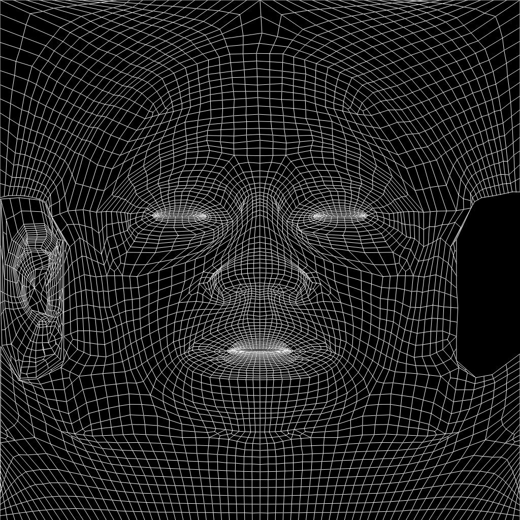
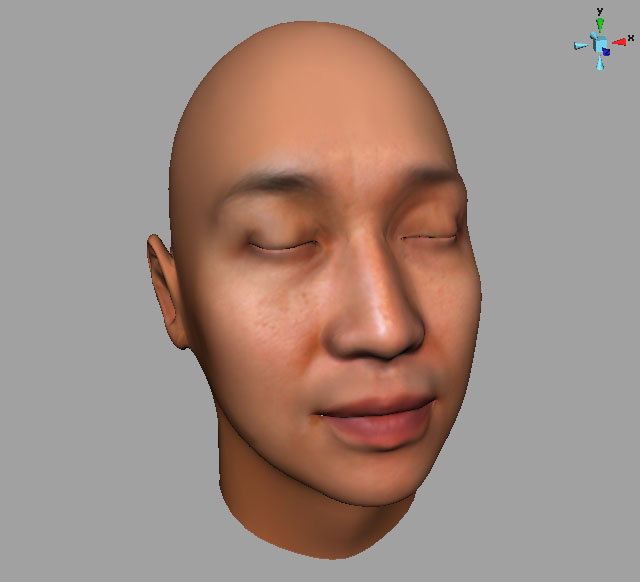
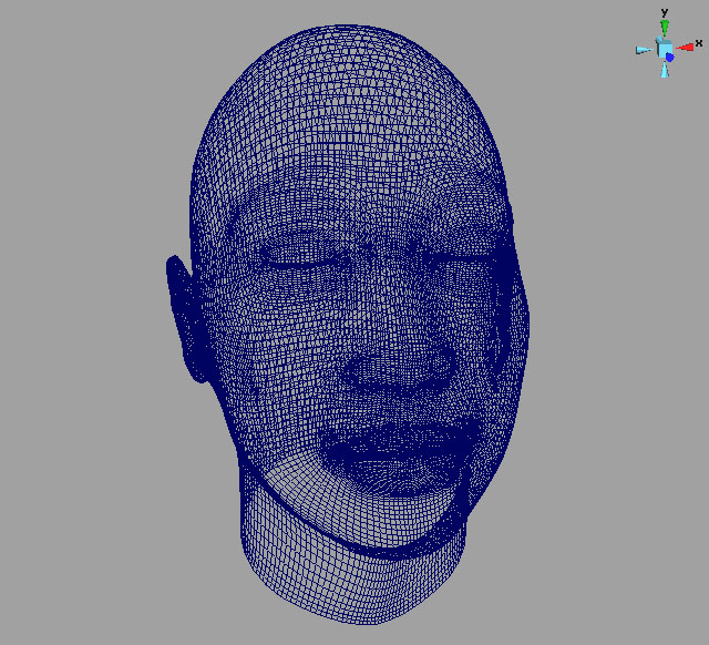
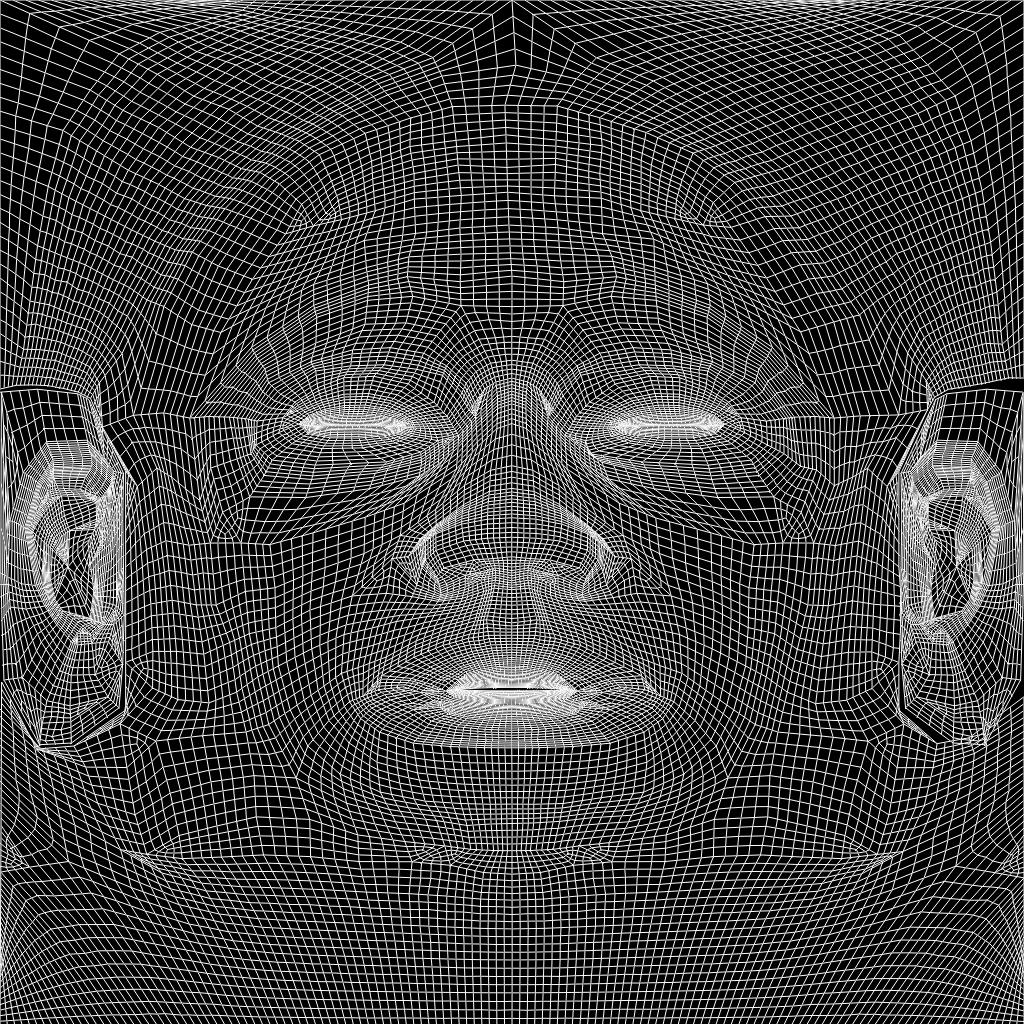
I used FaceGen software and my own two pictures (front and side) to generate head model. This software also provide color texture along with UV mapped mesh model. Below images are captured in Maya viewport (left smooth shading and center wireframe) and uv output (right image).
- Other Textures
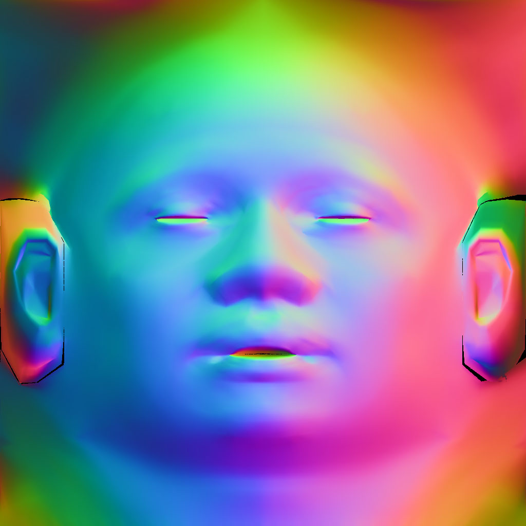
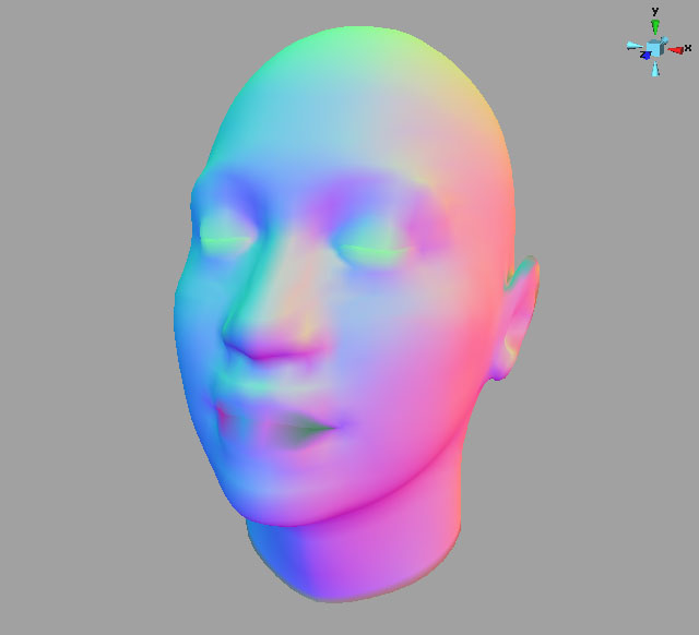
Original head texture is modified to separate each ears UV coordinate (original one has same coordinate for both ears). Since we process many of rendering operation on texture space, it was required to have all polygons has distinct, non-overlapped UV map. Also, object space based normal map is generated in Maya. There are couple of more offline texture images required but these will be explained in later sections.
The skin rendering in this work consists of two main parts. One is surface reflectance (specular surface reflectance) and anohter is subsurface scattering (diffuse subsurface scattering).
- Diffuse Subsurface Scattering
Since human skin is composed of multiple layers, we need to take this into accout to satisfy realistic light diffusion across face. Three layers model is used to calculate subsurface scattering, originally presented by [3]. One of very interesting aspect of GPU Gems3 model is that we can use linear gaussian convolution to obtain this scattering effectively and accurately. I will explain this in Section 4 in details.
- Specular Surface Reflectance
In this pass, we compute the amount of light reflects directly from skin surface without penetrate into flesh (known to be about 9%). More precise specular light model (Bidirectional Reflectance Distribution Function, BRDF) applied here to accurately obtain intensity of light. Will discuss further details in Section 5. later.
After these two main phases, we combine all light specular and diffusion result into final skin rendering shader. Implemented application heavily relies on image space (texture) operation so that bandwidth to sample texture data is the most important factor in performance. Therefore, performance and its quality depends on the resolution of intermediate render target object (RTT). I used 1024x1024 resultion while GPU Gems uses 4096x4096.
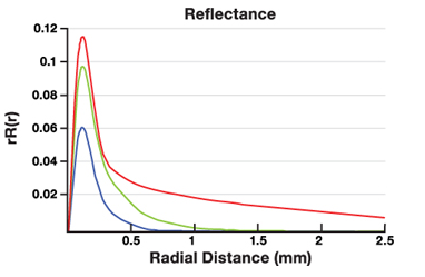
Now, we explain how to approximate the characteristics of human skin scattering. First of all, we introduce Diffusion Profile. Diffusion profile provides an approximation for the manner in which light scatters underneath the surface fo a hightly scattering translucent material [5]. For instance, when light beam hit a certain surface, scattering happens across radial distance from hit point. The amount of scatter from single light beam will be diminished as goes far from hit spot. This scattering is also strongly color dependent (red, green and blue profiles different from each other). Example from [5] illustrates this diffusion profile for three layered skin model.
(source: GPU Gems 3)
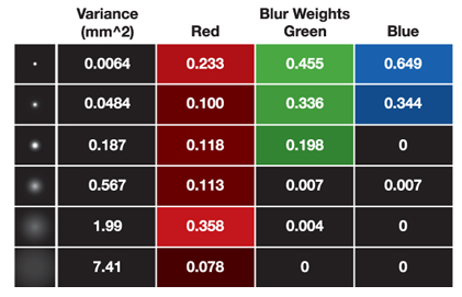
Eugene [5] found that three layered skin diffusion profile [3] can be approximated with linear sum of Gaussian funtion (convolution). They found that some of 6 Gaussian blur kernels fits the profile very closely. This is the whole idea of using multiple blur pass to get proper scattering amount. Here are those 6 kernels papameters used in this technique (left: blur kernel parameters, right: 3 layers skin profile).
(source: GPU Gems 3)
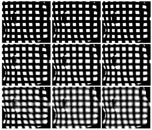
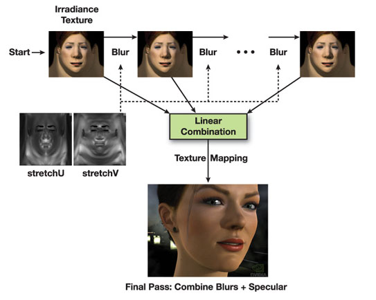
Since this blur kernel will be applied on texture space coordinate. We also need to take care of UV stretch across our head mesh. This is mainly because blur width is not uniformly applying with respect to 3 dimentional space. To be more precise, stretch factor of UV coordinate shoudl be considered in convolution kernel. Following image shows this process of sequential blurring (left) and the effect of stretch UV texture (right). Shader code follows after image.
(source: GPU Gems 3)
// compute stretch map values
float2 computeStretchMap( float3 worldCoord, float scale )

      {

      .... float3 derivu = ddx(worldCoord);

      .... float3 derivv = ddy(worldCoord);

      .... float stretchU = scale / length(derivu);

      .... float stretchV = scale / length(derivv);


      .... return float2 (stretchU, stretchV);		// two component texture color

      };
// vertex program

      v2f stretch_vp(a2v In,

      ............... uniform float4x4 model	// app specific model view matrix

      )

      {

      .... v2f Out;


      .... // transform position to world space

      .... float4 P = mul(model, In.Position);

      .... Out.P = v2t(In.TexCoord); ....... // convert model space to texture space

      .... Out.worldCoord = float3(P.xyz);
.... return Out;

      }
// fragment program

      float4 stretch_fp(v2f In,

      ................. uniform float scale) : COLOR

      {

      .... float2 outColor = computeStretchMap(In.worldCoord, scale);


      .... return float4(outColor.xy, 0.0, 1.0);

      }
In above code, v2t function takes texture coordinate and convert it to model space so that rendering result stays on 2D texture RTT. Following snippet shows this function code.
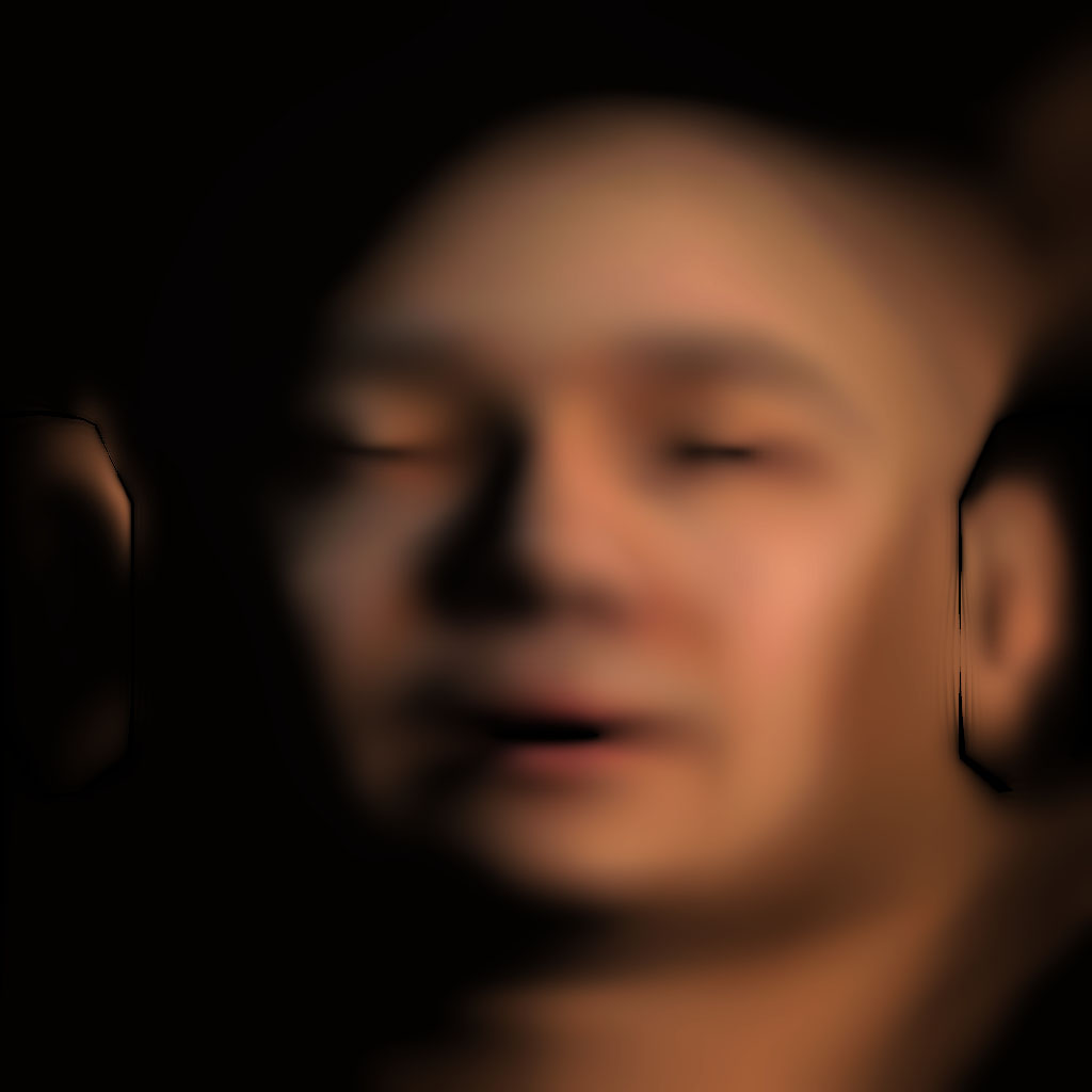
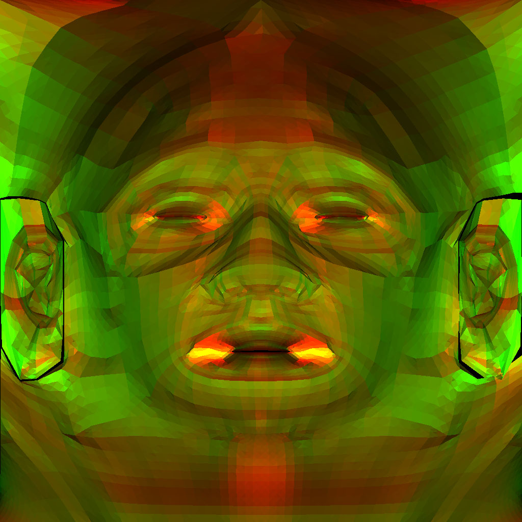
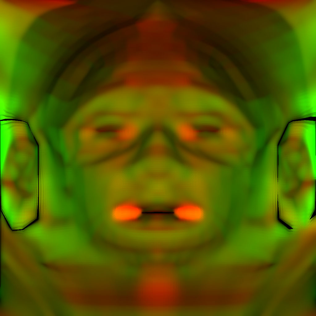
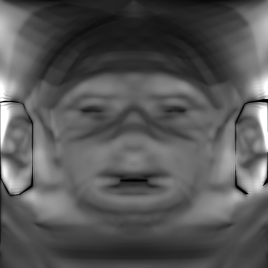
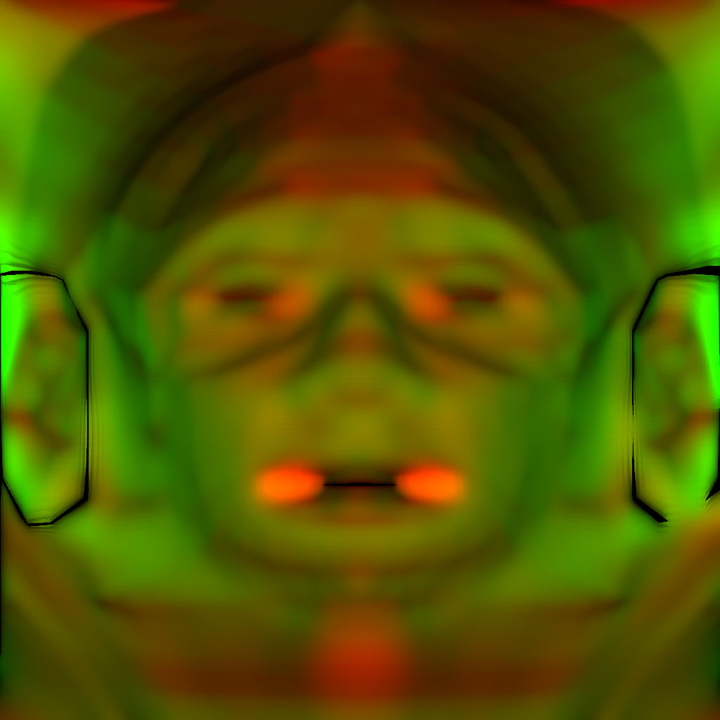
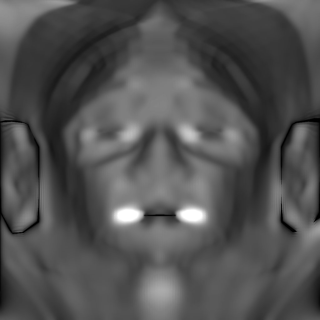
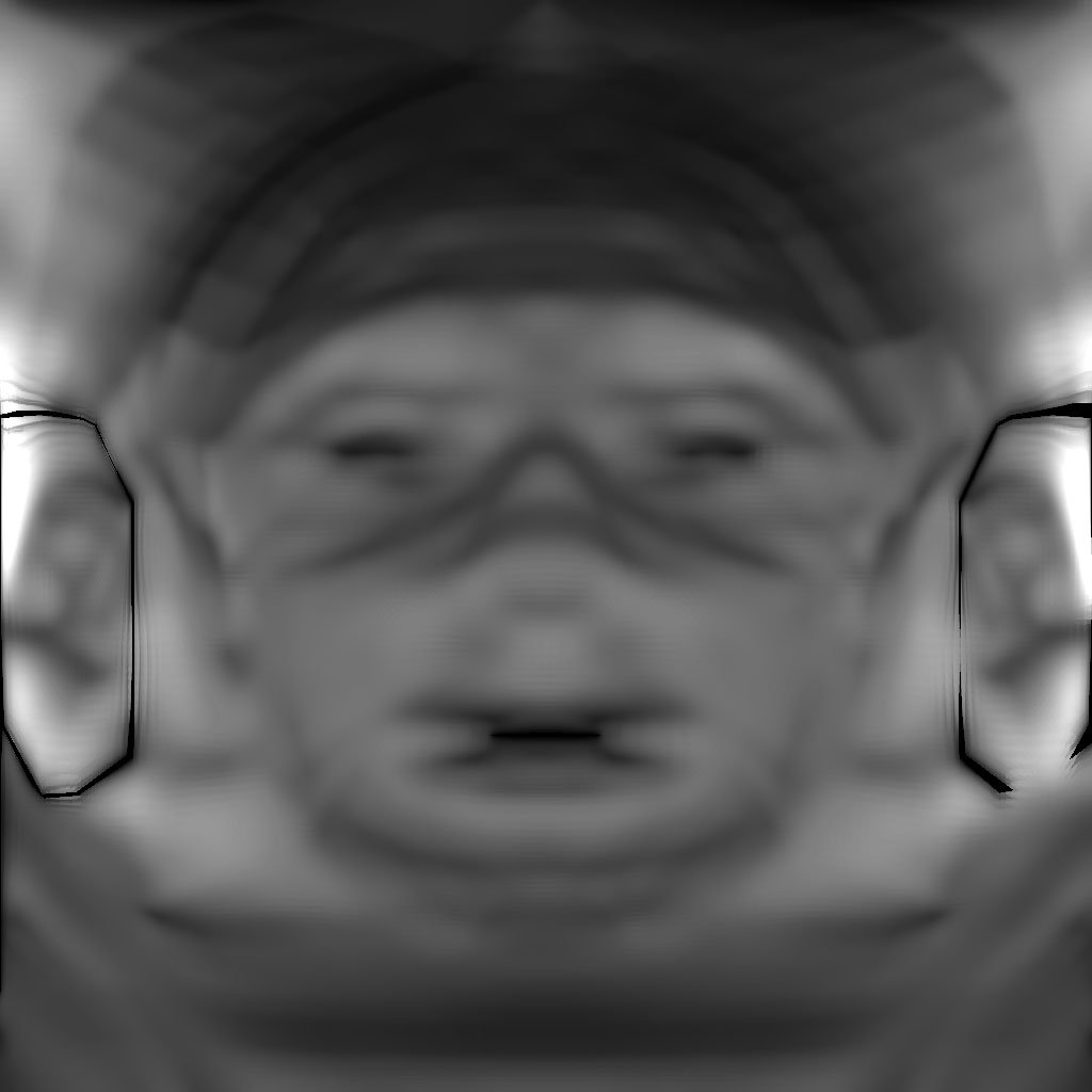
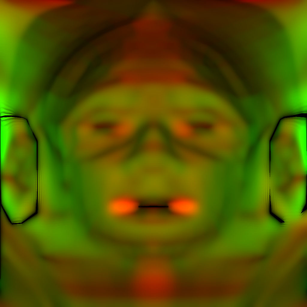
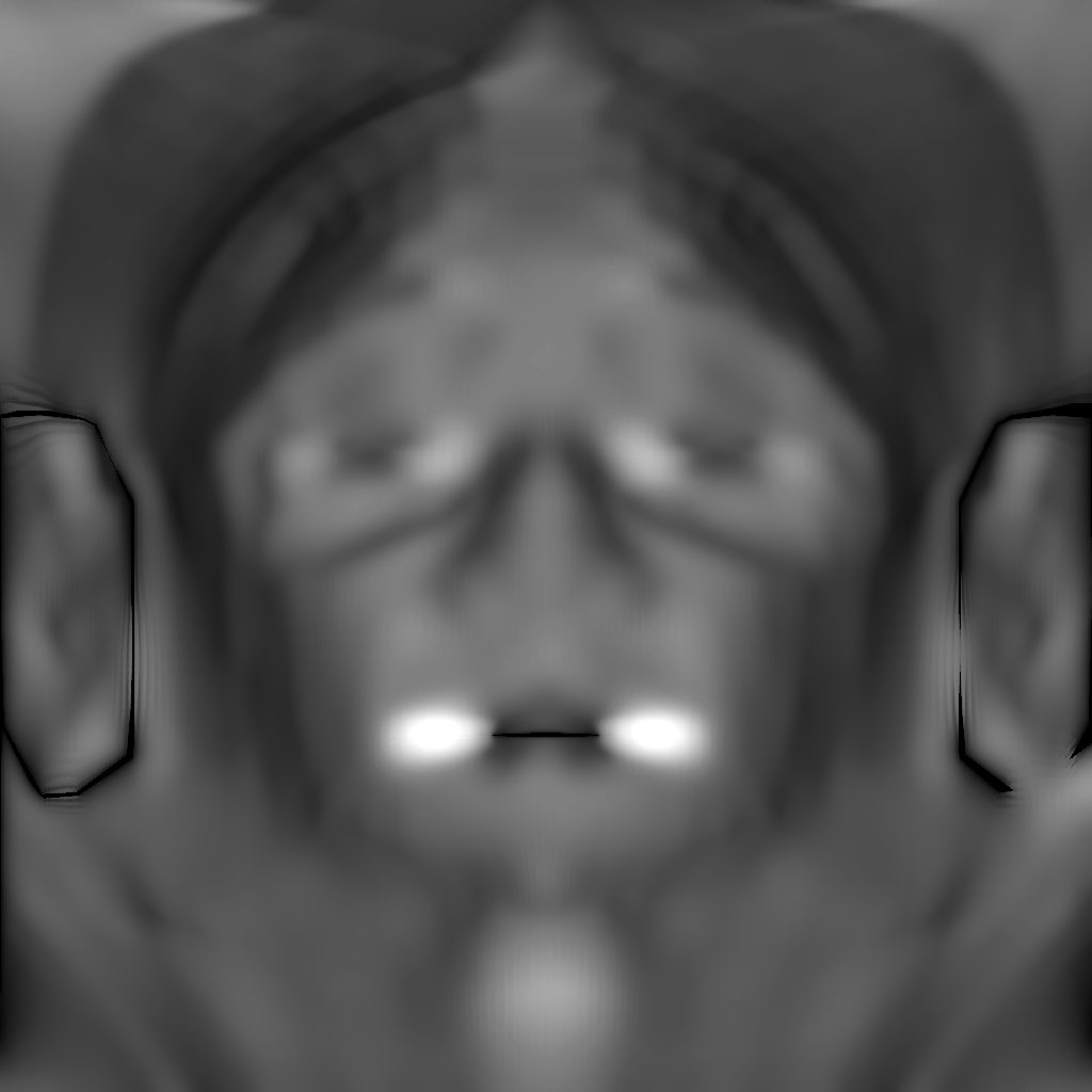
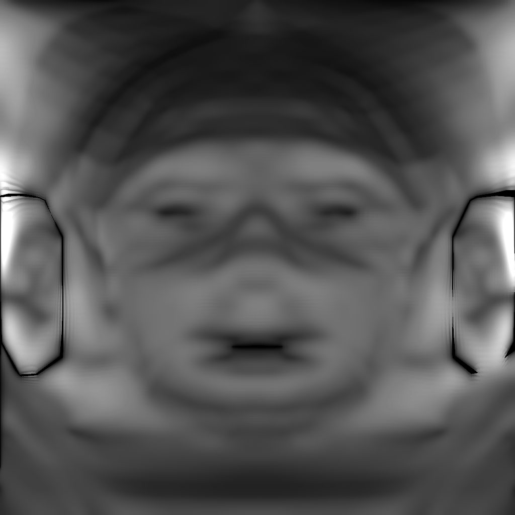
Below images shows each blur pass with UV stretch texture, U compont, V component, and Blurred Texture Space Rendering result (Irradiance map). To see larger image, click on each picture.
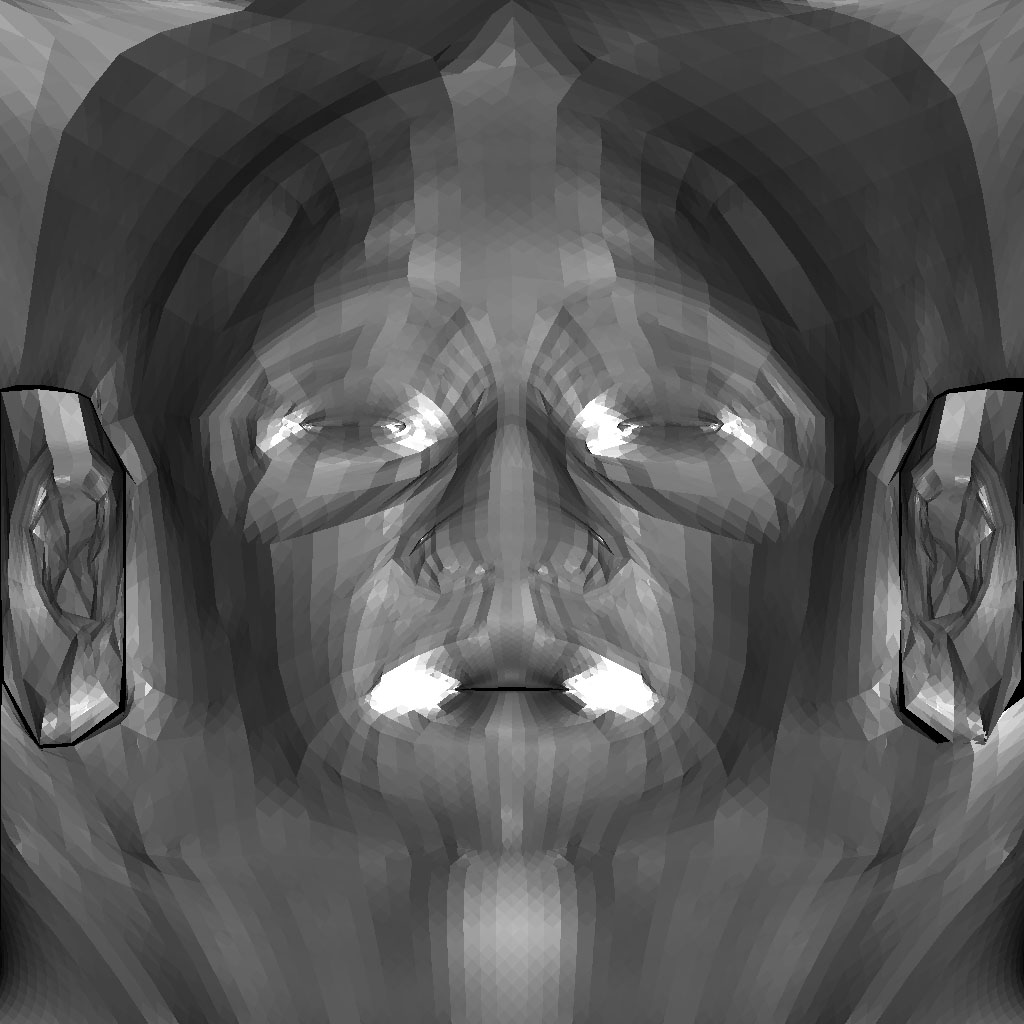
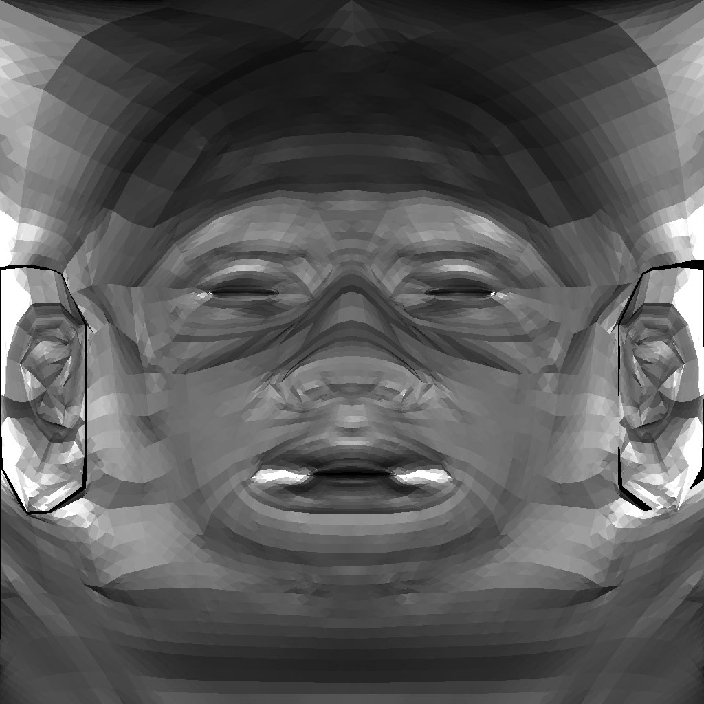
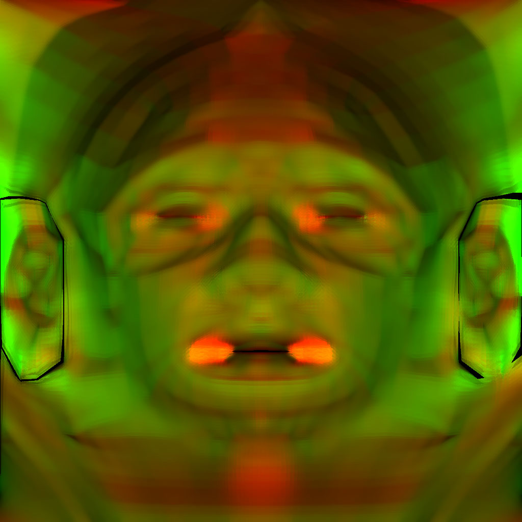

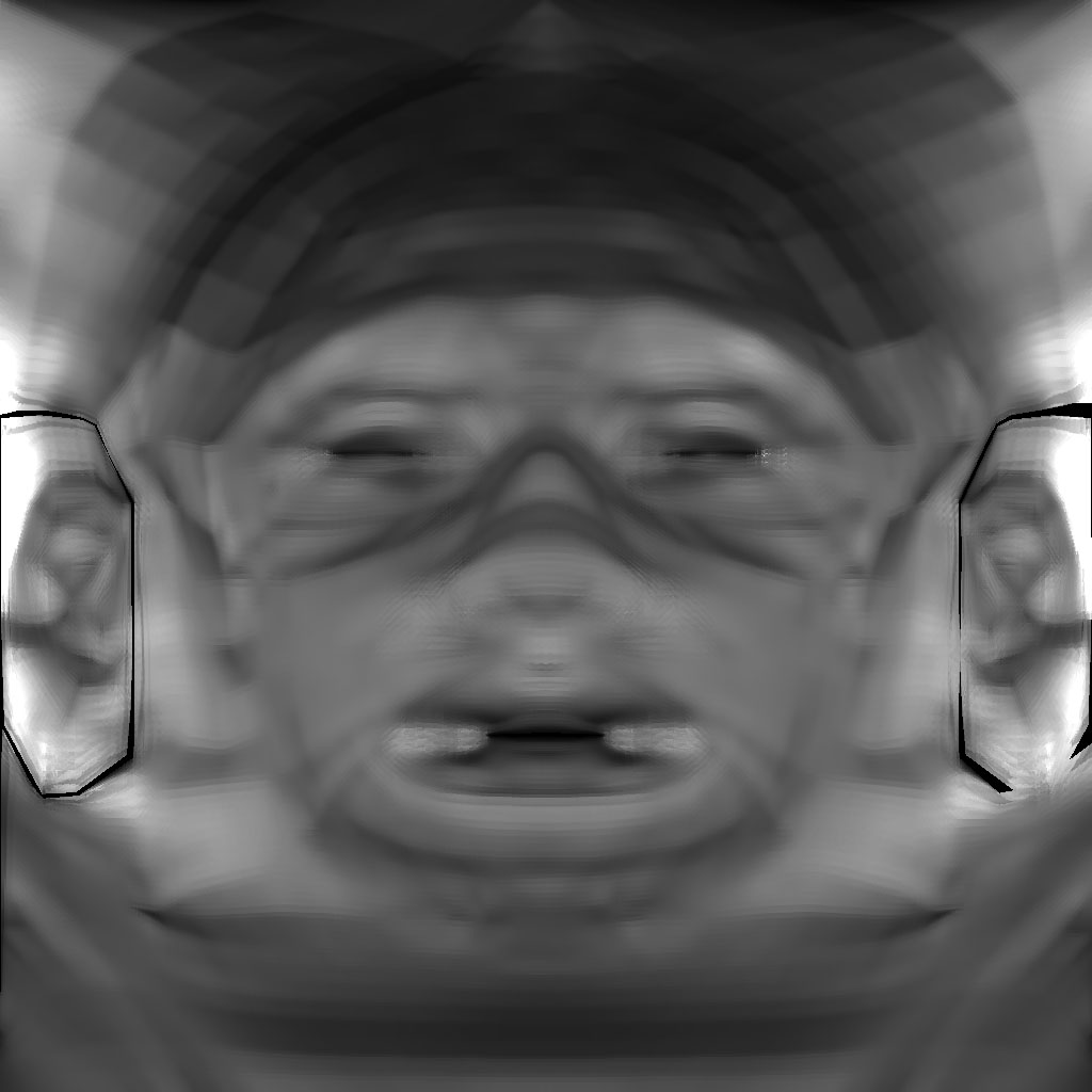

Gaussian convolution kernel used in application illustrated below.
// U direction blur
float4 convolveU_fp(float2 texCoord : TEXCOORD0,
................... uniform float GaussWidth,

      ................... uniform sampler2D inputTex		: TEXUNIT0,

      ................... uniform sampler2D stretchTex	: TEXUNIT1

      ................... ) : COLOR

      {

      .... float scaleConv = 1.0 / 1024.0;

      .... float4 stretch = f4tex2D(stretchTex, texCoord);

      .... float netFilterWidth = scaleConv * GaussWidth * stretch.x;


      .... // Gaussian curve - standard deviation of 1.0

      .... float curve[7] = {0.006, 0.061, 0.242, 0.383, 0.242, 0.061, 0.006};

      .... float2 coords = texCoord - float2(netFilterWidth * 3.0, 0.0);

      .... float4 sum = 0;


      .... for (int i=0; i<7; i++)

      .... {

      .... .... float4 tap = f4tex2D(inputTex, coords);

      .... .... sum += curve[i] * tap;

      .... .... coords += float2(netFilterWidth, 0.0);

      .... }


      .... return sum;

      }


      // V direction blur

      float4 convolveV_fp(float2 texCoord : TEXCOORD0,

      ................... uniform float GaussWidth,

      ................... uniform sampler2D inputTex		: TEXUNIT0,

      ................... uniform sampler2D stretchTex	: TEXUNIT1

      ................... ) : COLOR

      {

      .... float scaleConv = 1.0 / 1024.0;

      .... float4 stretch = f4tex2D(stretchTex, texCoord);

      .... float netFilterWidth = scaleConv * GaussWidth * stretch.y;


      .... // Gaussian curve - standard deviation of 1.0

      .... float curve[7] = {0.006, 0.061, 0.242, 0.383, 0.242, 0.061, 0.006};

      .... float2 coords = texCoord - float2(0.0, netFilterWidth * 3.0);


      .... float4 sum = 0;

      .... for (int i=0; i<7; i++)

      .... {

      .... .... float4 tap = f4tex2D(inputTex, coords);

      .... .... sum += curve[i] * tap;

      .... .... coords += float2(0.0, netFilterWidth);

      .... }
.... return sum;
}Each blurred image will be linearly summed in the final rendering kernel. In a single blurred image, we apply a given RGB weight to meet the skin profile.
- Translucent Shadow Map
Another interesting aspect of human skin diffusion is that there is possible light through a cetain thin part of face. For instance, ears. To include this effect, we modify shadow map to store efficient estimation of diffusion through thin regions. Instead of rendering z, normal and irradiance for each point on the surface nearest the light(light facing surface), as in a traditional translucent shadow map, we render z and the (u,v) coordinates of the light-facing surface. This allows each point in shadow to comptue a thickness through the object and to access the convolved irradiance textures on the opposite side of the surface, as shown in below figure [5]. See more details of this idean in the reference book.
(source: GPU Gems 3)
Physically based specular reflectance model is used in this process. Following is simple code to compute specular BRDF.
specularLight += lightColor * lightShadow * rho_s * specBRDF(N, V, L, eta, m) * saturate(dot(N, L) );
Constant rho_s is the term that scales light intensity. eta is index of reflection and m is roughness parameter. Interestingly BRDF can be computed efficiently by using precomputed Beckmann distribution texture (refer to Schlick's Fresnel approximation). This texture is combined with another 8bit color component of attenuation of diffuse light for the later pass for energy conservation. Following is the final specular function from the book.
float fresnelReflectance (float H, float3 V, float F0) // F0 is reflectance at normal incidence (for skin use 0.028)

    {

    ...float base = 1.0 - dot(V, H);

    ...float exponential = pow(base, 5.0);

    ...return exponential + F0 * (1.0 - exponential);

    }
float KS_Skin_Specular( float3 N, ....... // Bumped surface normal

    ........................float3 L, ....... // Points to light

    ........................float3 V, ....... // Points to eye

    ........................float m, ........ // Roughness

    ........................float rho_s, .... // Specular brightness (intensity scale)

    ........................uniform texobj2D beckmannTex )

    {
float result = 0.0;

      float ndotl = dot( N, L );
if( ndotl > 0.0 )

      {

      ....float3 h = L + V; // Unnormalized half-way vector

      ....float3 H = normalize( h );

      ....float ndoth = dot( N, H );

      ....float PH = pow( 2.0 * f1tex2D( beckmannTex, float2( ndoth, m ) ), 10.0 );

      ....float F = fresnelReflectance( H, V, 0.028 );

      ....float frSpec = max( PH * F / dot( h, h ), 0 );

      ....result = ndotl * rho_s * frSpec; // BRDF * dot( N, L) * rho_s

      }

      return result;
}
(source: Nvidia's Human Head Demo application)
- Varying Specular Parameters over the face
There was a study about human face skin surface reflectance (Weyrich, 2006). This study measured roughness (m) and intensity (rho_s) for most distict ten regions of the face across 149 faces [5]. Since this found that total 10 different constant values for m and rho_s, we can easily make this as texture to vary specular parameters when we calculate specular reflectance. Below images is this specular map.
(source: Nvidia's Human Head Demo)
Following code snippet is used in fragment program to feed specular reflectance function (KS_Skin_Specular).
// Specular Constant

      float4 specTap = f4tex2D( specTex, texCoord.xy ); // rho_s and roughness

      float m = specTap.w * 0.09 + 0.23;						// m is specular roughness

      float rho_s = specTap.x * 0.16 + 0.18;

      rho_s *= float( specTap.x > 0.1 );


      // Compute specular

      float3 specularLight = 0;

      specularLight += lightColor * lightShadow *

      KS_Skin_Specular(N, L, V, m, rho_s, rhodTex );
We looked through the Advanced Skin Rendering Technique in this project. Following is the summary of whole rendering pipeline
1. Render Shadow Map
2. Render Stretch correction map
3. Render irradiance into off-screen texture (RTT)
4. For each Gaussian kernel used in the diffusion profile approximation:
a. perform a separable blur pass in U
b. perform a separable blur pass in V
5. Render mesh in 3D
a. Access each Gaussian convolution texture and combine linearly
b. Add specular for each light source.
In Overall, we rendered scene (mesh) three times (shadow map, stretch correction, and final rendering) and performed texture space render pass 24 times (each convolution has two blur on stretch map UV and two blur on irradiance UV). Total number of Render to Texture (off-screen buffer) is about 18 including some of temporarily intermmediate textures.
Advanced Skin Rendering application is developed on windows XP using MS Visual Studio 2005 and nvidia's cg. There is no SW prerequisite to run compiled application but you needs nvidia cg SDK if you want to compile it by yourself. Application is tested with nvidia Geforce 8800 GTX and 8600 GT.
Download application source & executable.: AdvancedSkin.zip
To run applicaiton, execute bin/AdvancedSkin.exe
- Application Control
[Mouse]
Rotate: Alt + Mouse left button and move
Zoom: Alt + Mouse right button and move
Pan: Alt + Mouse middle button and move
[Key control]
'w' : toggle wireframe mode
'd' : toggle debug viewport rendering mode
'm' : toggle menu
[1] Subsurface Scattering, Wikipedia, http://en.wikipedia.org/wiki/Subsurface_scattering
[2] Henrik Wann Jensen, Subsurface Scattering, http://graphics.ucsd.edu/~henrik/images/subsurf.html
[3] Graig Donner, Henrik Wann Jensen, Light Diffusion in Multi-Layered Translucent Materials, ACM Trans. Graphic. (Proceedings of ACM SIGGRAPH 2005), 24(3):1032-1039, 2005
[4] Eugene d'Eon, Advanced Skin Rendering, GDC 2007 Demo Team Secrets
[5] Eugene d'Eon, David Luebke, Advanced Techniques for Realistic Real-Time Skin Rendering, GPU Gems 3, Addison Wesley, 2007