|
"Desktop Stempede"- A Boids Simulaiton -Mar, 2008Sangyoon Lee (sjames @ evl.uic.edu)Electronic Visualization LaboratoryUniversity of Illinois at Chicago |
This project is about making vivid desktop stempede in short. With boids simultion, subtle small desktop gadgets moves around desktop like flock of birds. So, what moves? "Dozens of Paperclips or Pencils or..."
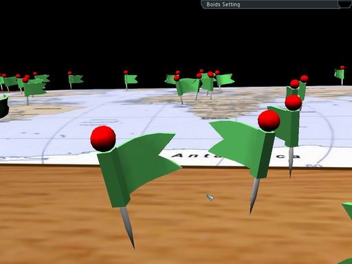
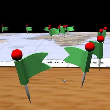
The story starts with small pins on world map. Flags... I am dreaming that I visit all countries in the world someday. Flag pins are markers that I wish to travel... all over the world. This short configuration makes the initial position of boids. Once simualtion starts, pins move freely as long as it obey the boids rules.
Mac App (Intel, Leopard): stempede_mac.zip
(unzip file and drag-n-drop stempede.app where you want to run. double click app)
Windows : stempede.zip
(download zip file, unzip, and exec. binary : .\stempede\build\win32\release\stempede.exe)s
Simulation algorithm is based on original Graig Raynolds' "Boids" idea. There are four main driver of this simulation, collision, cohesion, separation and alignment. With these four factors, global acceleration is accumulated for each boid object to change velocity later on. Since I implemented this simulation using Ogre library. All of evaluation rutines utilize Ogre Vector3, Quaternion, and Matrix rutine to compute simulation.
- Collision Detection (avoid scene obstacles)
There are two distinct object in the scene. One is flocking boid and the other is collision obstacles. Latter one represent any kind of desktop stationary that boid cannot pass through or jump over. Collision evaluation only support box shape in this version. In the possible collision case, simulation generate acceleration opposite to obstacle's normal vector (repulsion).
- Flockmates (visibility test)
In every iteration of simulation, boid visibility test is performed before getting into other evaluation rutine. This can reduce computation more effectively. Threee parameters are used to determine the visibility here. Velocity vector (heading of boid), range of vision (FOV) and distance of vision. This forms local area of interest for each boid to interact with neighbor boids.
- Cohesion (centering)Cohesion compute the center point among neighbors and generate local acceleration vector toward this point. The amount of acceleration is computed with the cohesion weight parameter.
- Separation (avoid crowding)Separation gives pleasant private space for each boids. This could be counter part of cohesion. Therefore, by changing its weight parameter with cohesion's one, boids may collide each other. During separation evaluation, simulation find the closest neighbor and apply weight toward the direction where they do not meet.
- Alignment (keep heading together)Alighment is similar to cohesion from the point of evaluation method (the original idea of "Boids"). Simulation compute mean of velocity (vector) among neighbors and uses it as acceleration. The other way around I used is simply only to considre the closest neighbor's direction. This also works well. Alignment also has its own weight factor so that we can easily change it to see the difference.
- Accumulation of AccelertionNow, we have four segment of local acceleration for each boid. Collision, Cohesion, Separation and Alignment. After running all those for evaluation, final acceleration is decided upon some priority rules. Each piece of acceleration ranges from 0.0 to 1.0 relative to max acceleration value. So, any one of value shows max (1.0) other local acceleration will be ignored. This approach gives better solution to avoid severe exception. Finally the acceleration determined with this accumulated value, max acc, max velocity, and desired max velocity.
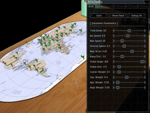
- Parameter ControlAs we have seen above, there are many parameters we may want to control to test different behavior of boids simulation. We can change these values through GUI. 12 parameters given here for you to play with.
- Debugging
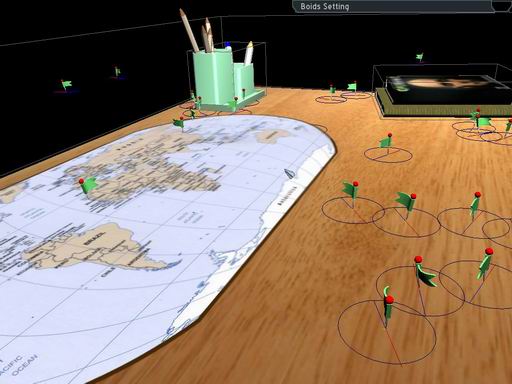
Sometimes it is hard to understand why certain boids moves like that. With small debug visuals, we are able to have better idea. User can see auxilarily components by enabling debug feature (on GUI or press 'D' key).
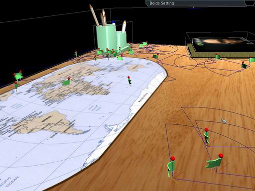
Velocity direction with speed (length of line. red line), Accumulated local acceleration (yellow line) and radar will be drawn together with models. Radar is result of FOV and distance of vision. Boids within this radar is the neighbors of the owner of radar.
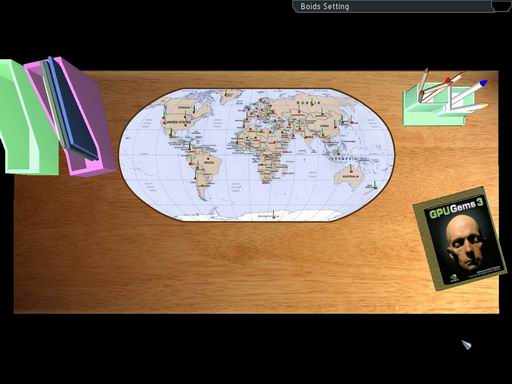
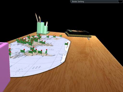
Simulation environments is relatively simple. It is common desktop. Ordinary stationeries...
Desktop is pretty much clean and empty to give more space for boids to move around not to be stuck in many spots (I have never had this clean desktop myself. -_-;). I used maya to model and animation object and blender (few times). After modeling and animation, all data were exported to Ogre file format via their plugin in maya.
- Model
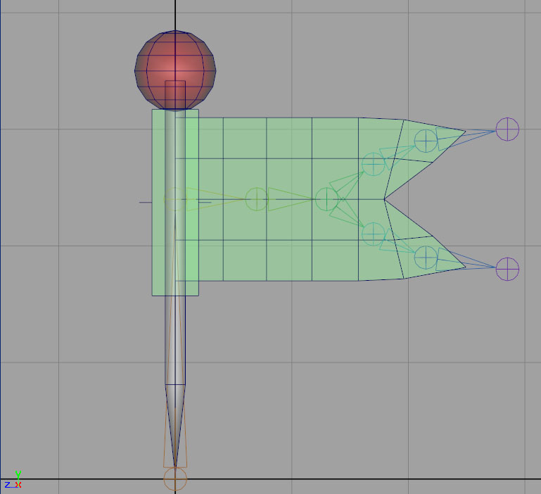
There are five models in the scene. Desk, some books, Magazine file, Pnecil cup and tiny flag pins ("the boid"). Most of model is stationary except our boid object.
- Animation
In the scene, only flag pin has animation to give a sense of movement (boid simulation). Each flag animation is designed in maya and application plays back it depends on boid movement. As simulation speed increases, flag's local animation gets faster.
Throught this project, there are some aspects that can be improved with more care. With limited project time, those consideration were not implemented in the final version but it would be nice to have them.
[Optimization]
Each rule of boids simulation has separate rutine to evalute the local acceleration in this version. Even with precomuted visibility test, there are still some of redundancy of computation in each rutine such as checkign visibility & activity flag and distance from neighbor. These repetition could be eliminated by integration of boids rule evaluator. I think that this minor optimizaiton could give slight performance gain on CPU time.
[Collision Detection for complex polygons]
Current implementation only support box type obstacle to compute collision (ray tracing against 6 flat sides). In general, boids simulation works well with simple bounding box scheme but more precise simulation might need to compute complex n-gon type obstacles. In this case, it would be easier to use Ogre ray tracing rutine.
[Veriety of Boids type & parameter]
To give more natural look and test other interaction, different types of boids is necessary such as predator (repulsing/avoiding), prey (attractor), and friend boid (normal flocking). Each boid has type for this but evaluation rutine (variation of acc caculation) is not implemented yet. In this version, pencil cup works as attractor.
One more missing part here is individual parameter settings. When I started design and implemtation, the idea was to give each boid separate parametes of simulation, mostly max values (velocity, acceleration, tendency of rule accumulation). It is implemented as designed but for parameter control later on, all boids use same values (becuase we cannot change each boid's parameter on the fly to see the difference. Sigle GUI gives all shared value among boids). Maybe slight random variation from shared parameter value be helpful.
- Boids, Graig Reynolds, http://www.red3d.com/cwr/boids/
Original Developer of Boids in 1986. (the proceedings of the ACM Siggraph conference)
- C++ Boids, Christopher Kline, http://www.behaviorworks.com/people/ckline/cornellwww/boid/boids.html
Boids Acceleration Accumulation method adopted.
- Ogre3D (Open Graphics Rendering Engine), http://www.ogre3d.org
Applicaiton built upon Ogre library (Platform Independent).
- Ray / Polygon intersection, Didier Badouel, Graphics Gems, Academic Press, 1990
Used to determine boid collision computation against obstacles