The VarrierTM Auto-Stereographic Display
Daniel J. Sandin, Todd Margolis, Greg Dawe, Jason Leigh, Thomas A. DeFanti
Electronic Visualization Laboratory
University of Illinois at Chicago
Abstract
The goal of this research is to develop a head-tracked, stereo virtual reality system utilizing plasma or LCD panels. This paper describes a head-tracked barrier auto-stereographic method that is optimized for real-time interactive virtual reality systems. In this method, a virtual barrier screen is created simulating the physical barrier screen, and placed in the virtual world in front of the projection plane. An off-axis perspective projection of this barrier screen, combined with the rest of the virtual world, is projected from at least two viewpoints corresponding to the eye positions of the head-tracked viewer. During the rendering process, the simulated barrier screen effectively casts shadows on the projection plane. Since the different projection points cast shadows at different angles, the different viewpoints are spatially separated on the projection plane. These spatially separated images are projected into the viewer’s space at different angles by the physical barrier screen.
The flexibility of this computational process allows more complicated barrier screens than the parallel opaque lines typically used in barrier strip auto-stereography. In addition this method supports the focusing and steering of images for a user’s given viewpoint, and allows for very wide angles of view. This method can produce an effective panel-based auto-stereo virtual reality system.
Keywords: Varrier, Barrier, Auto, Stereo, Stereographic, Display
1. INTRODUCTION
The main goal when generating imagery for virtual reality (VR) is to produce, in real-time, a series of continuous viewer-centered, wide-angle, stereoscopic images. Numerous techniques for presenting stereoscopic images have been implemented in the past. A overview of these techniques may be found in Sandin et al. [4]. More recently, the most commonly adopted method has been through the use of field-sequential stereo mediated by liquid crystal shutter glasses. In this system, pairs of stereoscopic images are presented to the viewer on a display screen, one at a time while the LCDs in the shutter glasses darken in synchrony with the images so that the correct image is provided to the correct eye. By performing this operation fast enough the brain fuses the two different images into a single apparently three-dimensional picture. Current VR systems that use this technology include the CAVETM [1] and ImmersaDeskTM [2] (Figure 1.) The ImmersaDesk3,TM [3] attempted to perform field-sequential stereo on a Plasma panel. For field-sequential stereo to be usable, the display has to update images at a minimum of 90Hz- twice the flicker fusion frequency. The plasma panel could only refresh at 60Hz. This produced too much flicker to be useable in stereo. Even if the plasma panel supported a higher display frequency the light from the phosphor decays so slowly that the differing eye’s images blend into each other (causing ghosting.) This is a problem in general with both Plasma and LCD panels, and hence motivates us to develop an alternative stereo delivery system.
The main drawback of using LCD glasses is that they are relatively costly, fragile and bulky. Passive stereo projection schemes using polarizing filters could be used to reduce such an encumbrance, however the goal is ultimately to provide stereo imagery for VR that can be viewed without requiring the use of special glasses. Barrier-strip technology offers that possibility. The barrier-strip method involves taking images of a scene from a predetermined set of viewpoints and interleaving them into vertical strips. To view the stereoscopic image, one surface of a transparent spacer is mounted with the resulting interleaved image, while the opposite face is mounted with a line screen. The panel is backlit in a light box and the viewer sees the stereogram through the slits of the line screen space- each eye receiving a slightly different image.
The new technique presented in this paper enhances the entire process
by providing a means for modern computer graphics hardware to perform real-time
image generation and interleaving, given any viewpoint. The resulting image is
viewed through a line screen placed over an LCD display panel rather than a
traditional light box. The user wears a 3D head tracking system to update the
computer on what his/her current viewpoint is, and the computer will generate
the new interleaved image to provide the expected view.
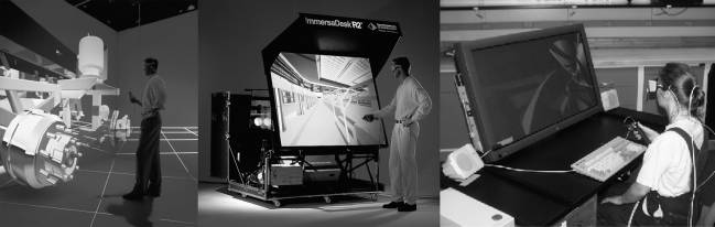
Figure 1 : Whereas the CAVE and ImmersaDesk 2 use projectors to display the field-sequential stereo, the ImmersaDesk 3 attempts field-sequential stereo with a Plasma panel. Plasma panels in general have phosphors that are too slow to support field-sequential stereo. The ImmersaDesk3 had too much ghosting and flicker to be useful in stereo.
2. VARRIER METHOD BY SIMULATING THE LINE
SCREEN
In the traditional pixel-aligned sorting method [4] the line screen distance of the barrier screen is the same as that of the interleaved images. The ratio of blocking and transparent lines (the duty cycle) on the barrier screen is usually 1/n where n is the number of interleaved images. Figure 2 shows the parallel channels that are produced by this scheme and how the two eyes see the correct images through the appropriate slits. Note however that as the viewer moves his/her head beyond the intended viewing angle the eyes will no longer receive the correct image and in fact may receive opposite images hence creating an depth-inverted, or pseudostereo, effect.
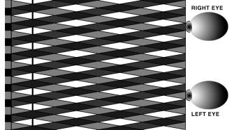
Figure 2 : Parallel image channels that are produced by the traditional pixel aligned sorting method.
The novelty of the Varrier technique over
previous techniques lies in the image generation and interleaving process. In
this technique, a virtual, variable barrier screen (Varrier) is created
simulating the physical barrier screen, and placed computationally in the
virtual world in front of the image plane (see Figure 3). An off-axis perspective projection of this barrier
screen, combined with the rest of the virtual world, is presented from at least
two viewpoints, which correspond to the eye positions of the viewer. During the
rendering process, the simulated barrier screen effectively “casts shadows” on
the image (projection) plane. Since the different projection points cast
shadows at different angles, the different viewpoints are spatially separated
on the image plane. These spatially separated images are presented in the
viewer's space at different angles by a physical barrier screen.
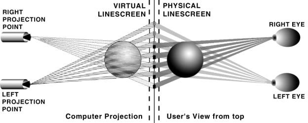
Figure 3 : On the left, a computer model of a sphere is perspective-projected onto the image plane from both the left and right eye positions. These positions correspond to the tracked positions of the viewer’s eyes in the real world. The virtual line screen casts shadows on the image plane such that the images become interleaved. On the right side the physical barrier screen reverses the process causing a reconstructed stereo view of the sphere. The right eye sees only the right eye’s view because the barrier screen blocks the left eye’s image. The left eye sees only the left eye’s view because the barrier screen blocks the right eye’s image.
The computer algorithm for the Varrier technique is as follows:
- Draw the line screen for one eye’s viewpoint into the Z buffer. The line screen, however is NOT drawn into the color buffer. Hence the line screen itself is not visible in the image, only the virtual scene that has filtered through the line screen. Draw the virtual scene for one eye’s viewpoint into the color buffer and Z buffer.
- Clear the Z buffer only.
- Draw the line screen into the Z buffer for the other eye’s viewpoint.
- Draw the virtual scene for the other eye’s viewpoint into the color buffer and Z buffer.
In a real-time, interactive VR system, this algorithm is repeated as rapidly as possible (preferably at a minimum of 30Hz to ensure smooth animation). An accurate head tracking system is needed to determine the current eye position of the viewer so that the correct series of image shadows are drawn.
A problem with this algorithm is that the line screen will not properly occlude virtual objects between the line screen and the projection point. A properly positioned and scaled line screen can be drawn near the moving projection point that will cast exactly the same shadows as a line screen fixed near the projection plane. Figure 4 shows the translation (Ex+(Sx-Ex)(ND/FD), Ey-(Sy-Ey)(ND/FD), Ez-(FD-ND)) and scaling ((FD/ND), (FD/ND), 1) that is needed to position the virtual line screen in front of the projection point.
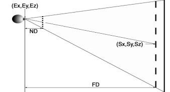
Figure 4
: Illustration of how the Varrier screen is
scaled and translated to a position near the moving projection
point. This produces the same shadows
as a fixed screen near the image plane but will properly occlude objects
between the screen and the projection point. (ND is the Near Distance, FD is
the Far Distance, E is the Eye position, S is the Screen position.)
3. EXPECTED ADVANTAGES & DISADVANTAGES
OF THE VARRIER METHOD
3.1. Advantages
The advantages of this computationally unified method include: automatic correction for the instantaneous position of the viewer, a non-uniform line screen, no cumbersome glasses needed, and compatibility with LCD panels. Neither the virtual nor the physical barrier strips need to be binary or uniform. They can be fuzzy or randomly positioned.
Uniform Computational Method - The chief advantage of the Varrier is that the
computational method used to draw off-axis perspective projections, required
for VR, is also used to draw the simulated line screen. In our implementation
the line screens were composed of approximately 400 polygons, a small number of
polygons compared to the hundreds of thousands typically in a VR scene.
Consequently, it is easy to perform the entire operation in real-time.
Wide Angle of View - The traditional pixel aligned sorting method
produces parallel channels of images projected into space, requiring that the
viewer stand far from the screen (see Figure 5). For example, if we were to attempt to use this
technique with our LCD screen: given a plexiglass spacer of 11/16” with a
refractive index of 1.49, the Spacer Thickness (ST = (11/16)/1.49); Line
Distance (LD) of 1/27.2” and Display Width (DW) of 14.4”.
The View Distance (VD) = DW * ST/LD = 180” or 15ft. This creates a
viewing angle of only 4.6 degrees.
One can see from Figure 6 that this limitation does not apply to the Varrier
method.
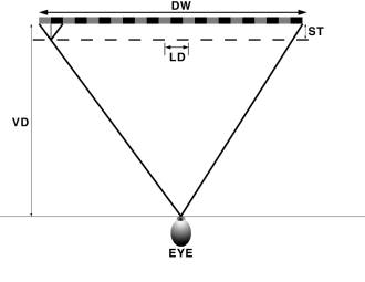
Figure 5 : The traditional
pixel aligned sorting method produces parallel channels of images projected
into space, requiring that the viewer stand far from the screen- hence angle of
view is small. If the eye gets closer to the screen than shown here, a pseudostereo
image will be seen at the outer margins of the image. (DW is Display Width; LD
is Line Distance; ST is Spacer Thickness; VD is Viewing Distance.)
Channels that Follow
the Viewer - As shown in Figure 3 and Figure
6 the images are projected out into space focusing on
the eyes of the viewer. With head-tracking the images will continue to follow
the eyes around the scene. Prior approaches [6,7] have accomplished this by moving the physical line
screen. In the Varrier method the interleaving computation is performed in the
image space (floating point) and not in the screen space (integer). However,
when the scene is written to the screen it is quantized by the pixel grid. From
the Nyquist sampling theorem there must be two samples for each image column to
preserve the continuous nature of the computation and subsequent steering of
channels. The low pass filtering
required to complete the process is supplied by the non-zero aperture of the
line screen. Described in another way (see Figure 7,) we can see that if one pixel is used for each eye’s
image, translating the viewer by half the interocular distance will cause each
eye to see a mix of the left and right eye’s image, producing a 100% ghost.
Doubling the number of pixels solves this problem.
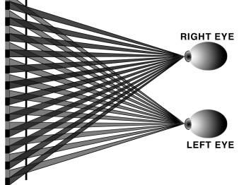
Figure 6 : Illustration of how Varrier images are projected
out into space focusing on the eyes of the viewer. Notice that at the widest
angles of view from each eye, the images are no longer uniformly aligned behind
each slit of the line screen.
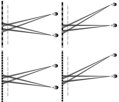
Figure 7 : If one pixel is used for each eye’s image (top two
diagrams), translating the viewer by half the interocular distance will cause
each eye to see a mix of the left and right eye’s image, producing a 100%
ghost. Doubling the number of pixels (bottom two diagrams) solves this problem.
Non-Uniform Screens
Can be Used - Since
the Varrier method computes a simulated screen, non-uniform and/or non-parallel
lines can be created to compensate for lens distortions when this technology is
applied to LCD projectors. To reduce moiré patterns, the barrier screen can
incorporate a continuous range of opacities (fuzzy borders), or a jittered line
pattern, instead of a purely uniform black/white pattern.
Non-Pixel Aligned
Screens - The line screen does not need to be pixel
aligned. It is difficult to generate screens that are precisely the pitch of
the display device. In our case, our pixel pitch is 111.1 pixels/in and the
pixel pitch of the scanner that generated the line screen is 406.8 pixels/in-
they are not integrally related.
Rotated Line Screens - In our implementation, the line screen was rotated at 30 degrees from the vertical axis. Rotating the line screen has many advantages. If the line screen is vertical, the moiré pattern caused by the difference of the two spatial frequencies of the pixel grid and line grid is concentrated into very visible vertical bars. Rotating the screen distributed the moiré patterns into a more subtle (but still visible when viewed closely) diamond pattern. Also in many LCD panels the RGB sub-pixels are arranged in vertical columns causing the interleaved display to have a hue shift from red to blue across the screen. Rotating the screen lowers the visibility of this hue shift dramatically. An additional advantage is that there is an exchange between vertical and horizontal resolution. An excellent description of this phenomenon is described in Van Berkel[5].
3.2. Disadvantages
The significant disadvantages of the
Varrier technique compared to field-sequential stereo are: lowered resolution
and high sensitivity to tracker latencies and errors. In addition a non-tracked
viewer of the display will see images that change from stereo- to pseudostereo
as the tracked viewer moves.
Low Resolution - Resolution is a scarce display resource. Any barrier strip technique requires dividing the resolution of the display by at least two. In the Varrier method the display resolution is divided by an additional factor of two to facilitate the steering of the image channels towards viewer. In the current prototype, the horizontal resolution of the display is divided by 3.6.
Additional Computational Overhead - All stereo processing requires two passes, one for each eye, doubling the rendering time. In The Varrier case one has to take additional time to draw the line screen twice as well- once for each eye. For our implementation, the Varrier was built out of approximately 400 polygons. This is a small number of polygons compared to the number of polygons that a modern graphics card can draw in real-time. However, since the line screen has a ¾ duty cycle, it will also cover three-quarters of the pixels on the screen. This large number of pixels may take significant processing time if the graphics processor is fill-limited.
Tethered Tracking – The Varrier works optimally when an accurate and timely measure of the viewer’s viewpoint is available. Unfortunately, this means that viewers must wear a tracking system even though they no longer have to wear special glasses to mediate the stereo.
High Sensitivity to Tracker Inaccuracies - If the tracking system has errors that are equal to the interocular distance (approximately 2.75 inches,) a pseudostereo image will result. To minimize ghosting the position of the eyes needs to be determined to a small fraction of the interocular distance. For the sake of argument, let us assume that the error is 0.5in. Although this may not sound like a stringent requirement, it does require a high quality tracking system to achieve.
High Sensitivity to Tracker Latencies - If a person moves one interocular distance in the time it takes to measure the eyes’ position, and draw the frame; a pseudostereo image will result. Again assuming that the tracker may err as much as 0.5in, a slowly moving person can easily move his/her head by 1 foot/second. This translates to a tracker latency and rendering time budget of approximately 40 milliseconds.
4. IMPLEMENTATION
We first experimented with a Pioneer Plasma panel (model PDP-V502X) driven by a Silicon Graphics Onyx with an Infinite Reality 2 graphics card. This system used a standard analog RGB video interface with the sync signal on the green channel. Initial experiments showed that errors in the sync extraction and pixel clock regeneration system of the display resulted in an image translation of more than a pixel with differing image content. Since geometric stability to a fraction of a pixel is required for Barrier strip autostereography to function, further work on this system was suspended. We do not believe that this problem precludes the use of analog interfaces between the computer and display. The Plasma display is much more stable with the 5-wire interface (R, G, B, horizontal sync, vertical sync) but a full digital interface eliminates some potential geometric instabilities.
The final working Varrier prototype was implemented with an SGI 320 PC and an SGI LCD panel display (model 1600SW.) The interface between the computer and display is a Digital Flat Panel interface. The 14.4" by 9.25" display has a resolution of 1600 by 1024 with a pixel pitch of 111.1 pixels/in. The RGB sub-pixels are organized horizontally.
The software system was implemented in OpenGL and the CAVElib library[1]. The tracking system used was an InterSense 900 with a published accuracy of 1.5mm and a latency of 10ms. A pre-press scanner on photographic film generated the barrier screen. The pitch of this scanner was 406.8 pixels/in.
Our best Varrier implementation so far utilizes a line screen of pitch 27.2 lines/in which is approximately 4 times the pixel spacing. This screen was rotated 30 degrees from the vertical creating a horizontal spacing of 3.51 pixels. The screen was ¾ opaque resulting in an open slit of approximately 0.87 pixels (the exact numbers are an accident of history.) In general, the system has approximately 2 pixels for each eye’s image and a transparent slit of approximately 1 pixel.
The spacer used between the display and the barrier was a 11/16” plexiglass sheet. Plexiglass has a refractive index of 1.49. To compensate for this the simulated barrier screen in the virtual world was placed closer to the projection plane by a factor of 1 over the refractive index.
For the system to function the virtual line screen has to be registered with the physical line screen in pitch, rotation angle and horizontal displacement. One of the advantages of the Varrier method is that the parameters of the virtual line screen can be modified in real-time by software to match the physical line screen. This calibration procedure is designed so that a person sits in a convenient viewing position and adjusts parameters using a joystick. The calibration image is composed of a full-screen of red for the left eye and a full-screen green for the right eye. The viewer adjusts parameters until the left eye sees a uniform red image over the entire screen, and the right eye sees a uniform green image over the entire screen. This calibration then holds for the entire viewing volume of the virtual scene.
5. CONCLUSIONS & FUTURE WORK
The Varrier method works well, producing good stereo separation and a large viewing volume. The cross-talk between the stereo images was a mere 4% measured at a 5 ft distance. At a viewing distance of 5 ft, good performance was maintained for horizontal and vertical viewer displacements of plus and minus 4ft. The far viewing distance was 9 ft and the near viewing distance was 2 ft- which is a sizeable viewing range. The image channels are smoothly steered around the viewing volume and stay well focused on the tracked eyes. These channels can be observed by darkening the room and placing a white sheet of paper near the tracker.
The beating of the line screen against the pixel grid causes moiré patterns. They are visible as a texture superimposed on the image. The low cost graphics adapter we used did not properly implement anti-aliasing. In the future, we plan to use a graphics subsystem with good anti-aliasing and experiment with barrier screens that have soft edges and non-uniform periods to reduce the visibility of the moiré patterns.
The overhead of drawing the simulated barrier screens limited the frame rate to about 10fps or 100ms rendering time. Our tracking system added a latency of about 50 ms. If a scene were displayed on one of our standard field-sequential stereo VR systems such as the CAVE or ImmersaDesk, this frame rate would be acceptable. On the Varrier prototype normal movement produced pseudostereo images. Faster rendering and predictive tracking schemes will be necessary.
In the future, we plan to implement a tiled multi-panel VR display with
close viewing distances to provide an effective desktop VR system supporting
stereo, head tracking and a wide angle of view. In addition, EVL is
aggressively pursuing a real-time camera-based, un-tethered tracking system in
the hopes that all physical encumbrances in the VR experience can eventually be
eliminated.
6. ACKNOWLEDGEMENTS
The research, collaborations, and outreach programs at the Electronic Visualization Laboratory (EVL) at the University of Illinois at Chicago are made possible by major funding from the National Science Foundation (NSF), awards EIA 9720351, EIA-9802090, EIA-9871058, ANI-9712283, ANI-9730202, and ACI-9418068, as well as NSF Partnerships for Advanced Computational Infrastructure (PACI) cooperative agreement ACI-9619019 to the National Computational Science Alliance. EVL also receives major funding from the US Department of Energy (DOE), awards 99ER25388 and 99ER25405, as well as support from the DOE’s Accelerated Strategic Computing Initiative (ASCI) Data and Visualization Corridor program.
In addition, EVL receives funding from Pacific Interface on behalf of NTT Optical Network Systems Laboratory in Japan.
The CAVE, ImmersaDesk, ImmersaDesk3 and Varrier are trademarks of the Board of Trustees of the University of Illinois.
7. REFERENCES
3.
D. Pape, J. Anstey, M. Bogucki, G. Dawe, T. DeFanti, A. Johnson,
D. Sandin, “The ImmersaDesk3 -
Experiences With A Flat Panel Display for Virtual Reality.” In the
proceedings of the Third International Immersive Projection Technology
Workshop, Stuttgart, Germany, May 10-11, 1999, pp. 107-112.