(includes text and images from "Computer Graphics: Principles and Practice" by Foley et all)
online, you can click here to see some images created by members of the Electronic Visualization Laboratory here at UIC. Each lecture has a different set of images (collect em all!)
Last time we talked briefly about the hardware and in particular about the frame buffer and how it physically works.
Now we move up a level of abstraction to talking about how lines and polygons are drawn in the frame buffer.
Then we will discuss how 2D and 3D models are converted into forms suitable for drawing into the frame buffer.
Then, after the midterm, we will discuss how to make these 2D and 3D models more realistic looking to the viewer.
but all of this depends on being able to manipulate the frame buffer correctly.
We like to think about a scene as mathematical primitives in a world-space. This scene is then rendered into the frame buffer. This allows a logical separation of the world from the view of that world.
mathematically, points are infinitely small
mathematically, line segments are infinitely thin
these mathematical elements need to be converted into discrete pixels
as usual, there is an obvious easy way of doing these conversions, and then there is the way it is actually done (for efficiency.)
take an analytic (continuous) function and convert (digitize) it so appropriate pixels can be illuminated in the frame buffer
In a language such as OpenGL a programmer can generate a 2D line segment in world-space with code like the following:
glEnd();
Polygons are single closed loops of line segments, usually drawn with their interiors filled.
In a language such as OpenGL polygons are very restricted to improve speed:

To generate the outline of a triangular 2D polygon in world-space using OpenGL a programmer can write code like the following:
glEnd();
To generate a filled triangular 2D polygon in world-space using OpenGL a programmer can write code like the following:
glEnd();
We will not limit ourselves to these 'easier' polygons.
How are line segments and polygons in world-space converted into illuminated pixels on the screen?
First these coordinates in world-space must be converted to coordinates in the viewport (ie pixel coordinates in the frame buffer.) This may involve the conversion from a 2D world to a 2D frame buffer (which we will study in a couple weeks), or the reduction from a 3D world to a 2D frame buffer (which we will study a couple weeks later.)
Then these coordinates in the viewport must be used to draw lines and polygons made up of individual pixels (rasterization.) This is the topic we will discuss now.
Most of the algorithms in Computer Graphics will follow the same pattern below. There is the simple (braindead) algorithm that works, but is too slow. Then that algorithm is repeatedly refined, making it more complicated to understand, but much faster for the computer to implement.
given a line segment from leftmost (Xo,Yo) to rightmost (X1,Y1):
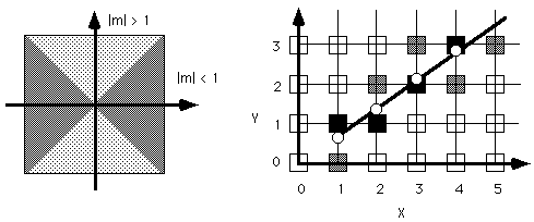
Assuming |m| <= 1 we start at the leftmost edge of the line, and move right one pixel-column at a time illuminating the appropriate pixel in that column.
start = round(Xo)
stop = round(X1)
for (Xi = start; Xi <= stop; Xi++)
Why is this bad? Each iteration has:
Addition is OK, fractional multiplication is bad, and a function call is very bad as this is done A LOT. So we need more complex algorithms which use simpler operations to decrease the speed.
Why is the slope (m) important?

if m=1 then each row and each column have a pixel filled in
if 0 <= m< 1 then each column has a pixel and each row has >= 1, so we increment X each iteration and compute Y.
if m > 1 then each row has a pixel and each column has >= 1, so we increment Y each iteration and compute X.

given a line segment from leftmost (Xo,Yo) to rightmost (X1,Y1):
Assuming |m| <= 1 we start at the leftmost edge of the line, and move right one pixel-column at a time illuminating the pixel either in the current row or an adjacent row.
starting at the leftmost edge of the line:
while (X <= X1) repeatedly
This guarantees there is one pixel illuminated in each column for the line
If |m| > 1 then we must reverse the roles of X and Y, incrementing Y by 1 and incrementing X by 1/m in each iteration.
Horizontal and vertical lines are subsets of the 2 cases given above.
need such a common, primitive function to be VERY fast.
features:

given a line segment from leftmost (Xo,Yo) to rightmost (X1,Y1):
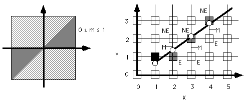
Assuming 0 <= m <= 1 we start at the leftmost edge of the line, and move right one pixel-column at a time illuminating the pixel either in the current row (the pixel to the EAST) or the next higher row (the pixel to the NORTHEAST.)
Y=mX+B
m = deltaY / deltaX = (Y1 - Yo) / ( X1 - Xo)
can rewrite the equation in the form: F(X,Y) = ax + by + c = 0
Y = (deltaY / deltaX) * X + B
0 = (deltaY / deltaX) * X - Y + B
0 = deltaY * X - deltaX * Y + deltaX * B
F(X,Y) = deltaY * X - deltaX * Y + deltaX * B
so for any point (Xi,Yi) we can plug Xi,Yi into the above equation and
Given that we have illuminated the pixel at (Xp,Yp) we will next either illuminate
To decide we look at the Midpoint between the EAST and NORTHEAST pixel and see which side of the midpoint the line falls on.
We create a decision variable called d
We plug the Midpoint into the above F() for the line and see where the midpoint falls in relation to the line.
d = F(Xp+1,Yp+0.5)
That tells us which pixel to illuminate next. Now we need to compute what Midpoint is for the next iteration.
if we pick the EAST pixel
We want to compute the new d without recomputing d from the new Midpoint
We want to compute the new d only using current d
dcurrent= F(Xp + 1,Yp + 0.5)
using the function F(X,Y) = deltaY * X - deltaX * Y + deltaX * B we can expand this out ...
dcurrent= deltaY * (Xp + 1) - deltaX * (Yp + 0.5) + deltaX * B
dnew = F(Xp + 2, Yp + 0.5)
dnew = deltaY * (Xp + 2) - deltaX * (Yp + 0.5) + deltaX * B
when you simplify it you end up with: dnew = dcurrent + deltaY
so we create a new variable called deltaE where deltaE = deltaY
if we pick the NORTHEAST pixel
We want to compute the new d without recomputing d from the new Midpoint, only using current d
We want to compute the new d only using current d
dcurrent= F(Xp + 1,Yp + 0.5)
using the function F(X,Y) = deltaY * X - deltaX * Y + deltaX * B we can expand this out ...
dcurrent= deltaY * (Xp + 1) - deltaX * (Yp + 0.5) + deltaX * B
dnew = F(Xp + 2, Yp + 1.5)
dnew = deltaY * (Xp + 2) - deltaX * (Yp + 1.5) + deltaX * B
when you simplify it you end up with: dnew = dcurrent + deltaY - deltaX
so we create a new variable called deltaNE where deltaNE = deltaY - deltaX
initial point (Xo,Yo) is known
so initial M is at (Xo + 1, Yo + 0.5)
so initial d = F(Xo + 1,Yo + 0.5)
using the function F(X,Y) = deltaY * X - deltaX * Y + deltaX * B we can expand this out ...
since (Xo,Yo) is on the line -> F(Xo,Yo) = 0
so initial d = deltaY - deltaX / 2
the division by 2 is still annoying, but we can remove it by being clever
we can avoid the division by 2 by multiplying F() by 2
this also multiplies d, deltaE, deltaNE by 2
but since d is only concerned with =0,< 0, or > 0 multiplication does not affect it
So now we can finally show the Midpoint Line algorithm
Assuming integral endpoints for the line segment (if not then make them integral)
starting at the leftmost edge of the line:
while (X < X1) repeatedly
else
illuminate X, Y
The full algorithm is given (in C) in the red book as program 3.2 on p.75.
The full algorithm is given (in Pascal) in the white book as figure 3.8 on p. 78.
features:
but that's not all!
What if the line segment starts on the right and proceeds to the left?
What about lines with slope < 0 or slope > 1? some modifications needed
want to avoid drawing pixels twice (not a problem with frame buffers but can be with other display technologies.)
pixels within the boundary of a polygon belong to the polygon
pixels on the left and bottom edges belong to a polygon, but not the pixels on the top and right edges
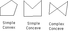
Want a polygon filling routine that handels convex, concave, intersecting polygons and poygons with interior holes.
overall algorithm:

specific algorithm:
Why do it horizontally, why not vertically?
Algorithm for step 1: scan-line algorithm
as usual there is the straightforward easy way and the convoluted efficient way.
an easy way:
More Polygon Filling, Clipping
last revision 8/30/03