(includes text and images from "Computer Graphics: Principles and Practice" by Foley et all)
online, you can click here to see some images created by members of the Electronic Visualization Laboratory here at UIC. Each lecture has a different set of images (collect em all!)
Last time we talked about how line segments are drawn into the frame buffer and began to talk about how polygons are filled in the frame buffer.
Today we will talk more about filling polygons and also discuss clipping ( what happens when the entire line segment or polygon does not lie within the frame buffer.)
From last time the specific polygon filling algorithm:
makes use of the fact that, similar to the midpoint algorithm, once we have an intersection we incrementally compute the next intersection from the current one. Xi+1 = Xi + 1/m
Create
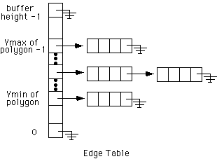
a global Edge Table (ET)

Lots of nagging little details for step 3:
- if intersection is at a noninteger value (say 4.6) is pixel 4 interior? is pixel 5 interior?
if we are outside the polygon (parity is even) then we round up
(pixel 5 is interior)
if we are inside the polygon (parity is odd) then we round down (pixel
4 is interior)
- if intersection is at an integer value (say 4.0)
- what if more than one vertex shares the same location? (this also handles the situation where you may end up with an odd number of edges in the AET)
- what if 2 vertices define a horizontal edge?
Example:

So the ET starts out being ...
------     ----------------     ----------------
| 20 | --> | 50 | 40 | -1 | --> | 40 | 40 | 0  |
------     ----------------     ----------------
------     ----------------     ----------------
| 10 | --> | 50 | 10 | 0  | --> | 40 | 70 | -1 |
------     ----------------     ----------------
and the horizontal line from (10,10) to (70,10) is ignored.
Why would this algorithm be much simpler if the polygon were guarenteed to be convext with no intersecting edges?
Since
we have a separation between the models and the image created from
those models, there can be parts of the model that do not appear in the
current view when they are rendered.
pixels outside the clip rectange are clipped, and are not displayed.
can clip analytically - knowing where the clip rectangle is clipping can be done before scan-line converting a graphics primitive (point, line, polygon) by altering the graphics primitive so the new version lies entirely within the clip rectangle
can clip by brute force (scissoring) - scan convert the entire primitive but only display those pixels within the clip rectangle by checking each pixel to see if it is visible.
as with scan conversion, this must be done as quickly as possible as it is a very common operation.
point
(X,Y)
clipping rectangle with corners (Xmin,Ymin) (Xmax,Ymax)
point
is within the clip rectangle if:
given a line segment, repeatedly:
Clip
rectangle extended into a plane divided into 9 regions
each region is defined by a unique 4-bit string
(the sign bit being the most significant bit in the binary representation of the value. This bit is '1' if the number is negative, and '0' if the number is positive.)
The frame buffer itself, in the center, has code 0000.
1001 | 1000 | 1010
-----+------+-----
0001 | 0000 | 0010
-----+------+-----
0101 | 0100 | 0110
For each line segment:
The
full algorithm is given (in C) in the red book as program 3.7 on p.105.
The full algorithm is given (in Pascal) in the white book as figure
3.41 on p.116.
Polygon Clipping and Fun with Circles