(includes text and images from "Computer Graphics: Principles and Practice" by Foley et all)
online, you can click here to see some images created by members of the Electronic Visualization Laboratory here at UIC. Each lecture has a different set of images (collect em all!)
Last time we talked about 2D and 3D transformations and how those transformations affect objects in the scene.
Today we are going to talk about how we convert a set of polygons in a 3D world into an image on a 2D screen.
Chapter 6 in the red version of the Foley vanDam book has SEVERAL errors in their implementation section. The white version of the Foley vanDam book (at least the Pascal version) does not have these errors. These errors are noted in the next set of class notes (lecture 8)
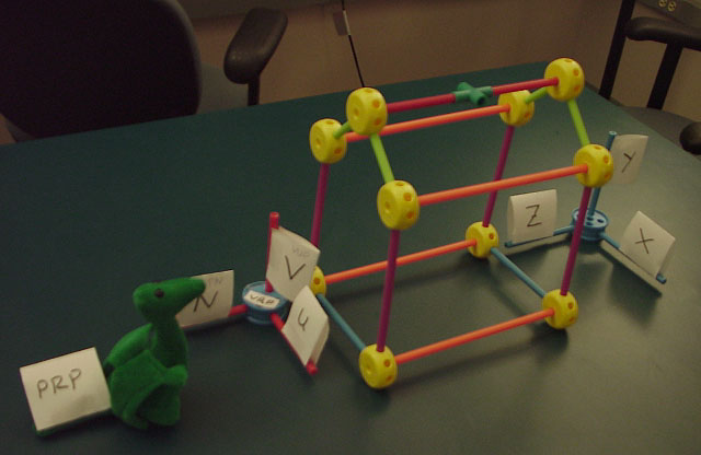
Tinkertoys are a really great way to learn about all these 3D concepts as you can build objects, and axis and look at them from different angles, and generally concretize all of the following.
UNfortunately Tinkertoys ain't what they used to be. They're plastic! They don't fit together as well! And you don't get enough of them! And while I can understand not wanting to kill a tree to make some tinkertoys, the plastic ones just aren't as good. Why in the old days we used to ....
So if you have some old wooded tinkerytoys, use them.
(In case you're curious, Lincoln Logs(tm) are plastic now too. sigh)
Taking 2D objects and mapping onto a 2D screen is pretty straightforward. The window is the same plane as the 2D world. Now we are taking 3D objects and mapping them onto a 2D screen.
Here is where the advantage of separating the model world from its rendered image becomes more obvious. The easiest way to think about converting 3D world into 2D image is the way we do it in real life - with a camera.
Lets say we have an object in the real world (e.g. the Sears Tower.) The tower sits there in its 3Dness. You can move around the tower, on the ground, on the water, in the air, and take pictures of it, converting it to a 2D image. Depending on where you put the camera and the settings on the camera, and other factors such as light levels, you get different looking images.
In the computer we have a synthetic camera taking still or moving pictures of a synthetic environment. While this synthetic camera gives you a much wider range of options than a real camera, you will find it is VERY easy to take a picture of nothing at all.
And a quick trip to the Renaissance ...

Albrecht Dürer, Daraughsman Drawing a Recumbent Woman (1525) Woodcut illusion from 'The Teaching of Measurements.'
projection is 'formed' on the view plane (planar geometric projection)
rays (projectors) projected from the center of projection pass through each point of the models and intersect projection plane.
Since everything is synthetic, the projection plane can be in front of the models, inside the models, or behind the models.
2 main types: perspective projection and parallel projection.
perspective :
which type of projection is used depends on the needs of the user - whether the goal is the mathematically correct depiction of length and angles, or a realistic looking image of the object.
Danger, watch out for acronyms being tossed out!
Need
to know the type of projection
Need to know the clipping volume
in
OpenGL there are the following functions:
View Plane defined by:
view plane can be anywhere in the world-space
The center of projection represents the location of the viewer's eye or the camera's lens.
Need
to define a 3D Viewing Reference Coordinate system (VRC) which
has axis u, v, n
since the View Plane (n=0) is infinite (as it is a plane) we need to declare a region of that plane to be our window.
Projection Reference Point (PRP) defines the Center of Projection and Direction of Projection (DOP)
Perspective projections categorized by the number of axis the view plane cuts (ie 1-point perspective, 2-point perspective or 3-point perspective)
if the plane cuts the x and z axis then lines parallel to the x axis or the z axis will meet at infinity; lines parallel to the y axis will not meet at infinity because they are parallel to the view plane. This is 2-point perspective.
if the plane cuts the x, y, and z axis then lines parallel to the x, y, or z axis will meet at infinity. This is 3-point perspective.
The n-point perspectives can work with any combination of the x, y, z axis.
The
view volume in orthographic projection:
The
view volume in perspective projection:
The
front plane's location is given by the front distance F relative to the
VRP
The back plane's location is given by the back distance B relative to
the VRP
In both cases the positive direction is in the direction of the VPN
Viewing
volume has 6 clipping planes (left, right, top, bottom, near (hither),
far (yon)) instead of the 4 clipping lines we had in the 2D case, so
clipping is a bit more complicated
In
the red version of the Foley vanDam book see P.211-212.
In the white version of the Foley vanDam book see P.250-252.
Here are some examples using the same house as in the book (figure 6.18 in the red version of the Foley vanDam book, figure 6.24 in the white version of the Foley vanDam book, but using my solution to the former HW3 as the viewing program:
The object is a house with vertices:
 0, 0,30
16, 0,30
16,10,30
 8,16,30
 0,10,30
 0, 0,54
16, 0,54
16,10,54
 8,16,54
 0,10,54
VRP= 0 0 54      or    VRP= 8 7 54
VPN= 0 0  1            VPN= 0 0  1
VUP= 0 1  0            VUP= 0 1  0
PRP= 8 7 30            PRP= 0 0 30

U: -1 to 17            U: -9 to 9
V: -2 to 16            V: -9 to 9
VRP= 16 0 54
VPN= 1  0  0
VUP= 0  1  0
PRP= 12 8 16

U: -1 to 25
V: -5 to 21
VRP= 16 0 54
VPN= 1  0  1
VUP= 0  1  0
PRP= 6  8 10

U: -22 to 22
V:  -2 to 18
For
other examples, in the red version of the Foley vanDambook see
P.206-211.
In the white version of the Foley vanDam book see P.245-250.
In
the red version of the Foley vanDam book see P.212-213.
In the white version of the Foley vanDam book see P.253.
with lots and lots of matrices.
Method 1:
Method 2:
How we implement these ideas