vtk
can
be obtained from http://www.vtk.org/
After you grab the
source you should build yourself a copy. In
the past we have found that doing an out-of-source build is better ...
install cmake if
you don't already have it (you can use macports to install it under
os-x)
mkdir VTK-build
cd VTK-build
ccmake ../VTK
BUILD_EXAMPLES ON,
VTK_WRAP_TCL ON
and maybe VTK_WRAP_JAVA and VTK_WRAP_PYTHON if you plan to use either
of those langauges.
and then you should
have a makefile that you can make install - this might take a while
and then you may
need to set your paths to make sure that the VTK-build/bin directory is
included, e.g under OS-X I need to make sure that DYLD_LIBRARY_PATH
includes /usr/local/VTK-build/bin
You
can
use vtk with C++, Tcl, Python, and Java.
VTK
comes
with
an
example
directory
and
one
of the simplest ways to test
your vtk install is to try running the Tcl examples. For example you
can cd to VTK/Examples/Medical/tcl and then vtk Medical1.tcl
To compile the cxx examples you should be able to go into the cxx directory and type "cmake ." and then "make".
Then
you
can
run
medical
example
1
in
VTK/Examples/Medical/Cxx
with
./Medical1 /usr/local/vtkData/DATA/headsq/quarter
Medical2,
3,
and
4
show progressively more complicated visualizations
//
The
following
reader is used to read a series of 2D slices (images)
// that compose the volume. The slice dimensions are set, and the
:/*=========================================================================
Program: Visualization Toolkit
Module: Medical1.cxx
Copyright (c) Ken Martin, Will Schroeder, Bill Lorensen
All rights reserved.
See Copyright.txt or http://www.kitware.com/Copyright.htm for details.
This
software
is
distributed WITHOUT ANY WARRANTY; without even
the
implied
warranty
of MERCHANTABILITY or FITNESS FOR A PARTICULAR
PURPOSE.
See
the
above copyright notice for more information.
=========================================================================*/
//
//
This example reads a volume dataset, extracts an isosurface that
//
represents the skin and displays it.
//
#include <vtkRenderer.h>
#include <vtkRenderWindow.h>
#include
<vtkRenderWindowInteractor.h>
#include
<vtkVolume16Reader.h>
#include
<vtkPolyDataMapper.h>
#include <vtkActor.h>
#include
<vtkOutlineFilter.h>
#include <vtkCamera.h>
#include <vtkProperty.h>
#include
<vtkPolyDataNormals.h>
#include
<vtkContourFilter.h>
#include <vtkSmartPointer.h>
int main (int argc, char *argv[])
{
if (argc < 2)
{
cout <<
"Usage: " << argv[0] << " DATADIR/headsq/quarter" <<
endl;
return
EXIT_FAILURE;
}
// Create the renderer, the render window, and the interactor. The
renderer
// draws into the render window, the interactor enables mouse- and
// keyboard-based interaction with the data within the render window.
//
vtkSmartPointer<vtkRenderer> aRenderer =
vtkSmartPointer<vtkRenderer>::New();
vtkSmartPointer<vtkRenderWindow> renWin =
vtkSmartPointer<vtkRenderWindow>::New();
renWin->AddRenderer(aRenderer);
vtkSmartPointer<vtkRenderWindowInteractor> iren =
vtkSmartPointer<vtkRenderWindowInteractor>::New();
iren->SetRenderWindow(renWin);
// The following reader is used to read a series of 2D slices (images)
// that compose the volume. The slice dimensions are set, and the
// pixel spacing. The data Endianness must also be specified. The reader
// uses the FilePrefix in combination with the slice number to construct
// filenames using the format FilePrefix.%d. (In this case the
FilePrefix
// is the root name of the file: quarter.)
vtkSmartPointer<vtkVolume16Reader> v16 =
vtkSmartPointer<vtkVolume16Reader>::New();
v16->SetDataDimensions
(64,64);
v16->SetImageRange
(1,93);
v16->SetDataByteOrderToLittleEndian();
v16->SetFilePrefix
(argv[1]);
v16->SetDataSpacing
(3.2, 3.2, 1.5);
// An isosurface, or contour value
of 500 is known to correspond to the
// skin of the patient. Once generated, a vtkPolyDataNormals filter is
// is used to create normals for smooth surface shading during
rendering.
vtkSmartPointer<vtkContourFilter> skinExtractor =
vtkSmartPointer<vtkContourFilter>::New();
skinExtractor->SetInputConnection(v16->GetOutputPort());
skinExtractor->SetValue(0, 500);
vtkSmartPointer<vtkPolyDataNormals> skinNormals =
vtkSmartPointer<vtkPolyDataNormals>::New();
skinNormals->SetInputConnection(skinExtractor->GetOutputPort());
skinNormals->SetFeatureAngle(60.0);
vtkSmartPointer<vtkPolyDataMapper> skinMapper =
vtkSmartPointer<vtkPolyDataMapper>::New();
skinMapper->SetInputConnection(skinNormals->GetOutputPort());
skinMapper->ScalarVisibilityOff();
vtkSmartPointer<vtkActor> skin =
vtkSmartPointer<vtkActor>::New();
skin->SetMapper(skinMapper);
// An outline provides context around the data.
//
vtkSmartPointer<vtkOutlineFilter> outlineData =
vtkSmartPointer<vtkOutlineFilter>::New();
outlineData->SetInputConnection(v16->GetOutputPort());
vtkSmartPointer<vtkPolyDataMapper> mapOutline =
vtkSmartPointer<vtkPolyDataMapper>::New();
mapOutline->SetInputConnection(outlineData->GetOutputPort());
vtkSmartPointer<vtkActor> outline =
vtkSmartPointer<vtkActor>::New();
outline->SetMapper(mapOutline);
outline->GetProperty()->SetColor(0,0,0);
// It is convenient to create an initial view of the data. The
FocalPoint
// and Position form a vector direction. Later on (ResetCamera() method)
// this vector is used to position the camera to look at the data in
// this direction.
vtkSmartPointer<vtkCamera> aCamera =
vtkSmartPointer<vtkCamera>::New();
aCamera->SetViewUp (0,
0, -1);
aCamera->SetPosition
(0, 1, 0);
aCamera->SetFocalPoint
(0, 0, 0);
aCamera->ComputeViewPlaneNormal();
aCamera->Azimuth(30.0);
aCamera->Elevation(30.0);
// Actors are added to the renderer. An initial camera view is created.
// The Dolly() method moves the camera towards the FocalPoint,
// thereby enlarging the image.
aRenderer->AddActor(outline);
aRenderer->AddActor(skin);
aRenderer->SetActiveCamera(aCamera);
aRenderer->ResetCamera
();
aCamera->Dolly(1.5);
// Set a background color for the renderer and set the size of the
// render window (expressed in pixels).
aRenderer->SetBackground(.2, .3, .4);
renWin->SetSize(640,
480);
// Note that when camera movement occurs (as it does in the Dolly()
// method), the clipping planes often need adjusting. Clipping planes
// consist of two planes: near and far along the view direction. The
// near plane clips out objects in front of the plane; the far plane
// clips out objects behind the plane. This way only what is drawn
// between the planes is actually rendered.
aRenderer->ResetCameraClippingRange ();
// Initialize the event loop and then start it.
iren->Initialize();
iren->Start();
return EXIT_SUCCESS;
}
To
make
a
new
C
project
(adapted
from
https://visualization.hpc.mil/wiki/VTK_in_CPP)
cmake_minimum_required(VERSION 2.6)
PROJECT(Test)
FIND_PACKAGE(VTK REQUIRED)
INCLUDE(${VTK_USE_FILE})
ADD_EXECUTABLE(Test Test.cpp)
TARGET_LINK_LIBRARIES(Test vtkHybrid)
e.g.
cmake_minimum_required(VERSION
2.6)
PROJECT(Cone)
FIND_PACKAGE(VTK REQUIRED)
INCLUDE(${VTK_USE_FILE})
ADD_EXECUTABLE(Cone Cone.cxx)
TARGET_LINK_LIBRARIES(Cone vtkHybrid)
2.
Create
a
sample
cpp
file,
or
copy
one
form the examples directory like
Cone.cxx
#include
<vtkConeSource.h>
#include
<vtkPolyData.h>
#include
<vtkSmartPointer.h>
#include
<vtkPolyDataMapper.h>
#include
<vtkActor.h>
#include
<vtkRenderWindow.h>
#include
<vtkRenderer.h>
#include
<vtkRenderWindowInteractor.h>
int main(int,
char *[])
{
//Create
a
cone
vtkSmartPointer<vtkConeSource> coneSource =
vtkSmartPointer<vtkConeSource>::New();
coneSource->Update();
//Create
a
mapper
and
actor
vtkSmartPointer<vtkPolyDataMapper> mapper =
vtkSmartPointer<vtkPolyDataMapper>::New();
mapper->SetInputConnection(coneSource->GetOutputPort());
vtkSmartPointer<vtkActor> actor =
vtkSmartPointer<vtkActor>::New();
actor->SetMapper(mapper);
//Create
a
renderer,
render
window, and interactor
vtkSmartPointer<vtkRenderer> renderer =
vtkSmartPointer<vtkRenderer>::New();
vtkSmartPointer<vtkRenderWindow> renderWindow =
vtkSmartPointer<vtkRenderWindow>::New();
renderWindow->AddRenderer(renderer);
vtkSmartPointer<vtkRenderWindowInteractor> renderWindowInteractor
=
vtkSmartPointer<vtkRenderWindowInteractor>::New();
renderWindowInteractor->SetRenderWindow(renderWindow);
//Add
the
actors
to
the scene
renderer->AddActor(actor);
renderer->SetBackground(.3, .2, .1); // Background color brown
//Render
and
interact
renderWindow->Render();
renderWindowInteractor->Start();
return
EXIT_SUCCESS;
}
3. type "cmake ." to create the Makefile.
4.
"make"
to
build
the
application
5.
run
the
application
(./Test)
and
you
should see a grey cone on a brown background
6.
make
changes
as
needed
another useful piece of code for dealing with image data, and in
particular doing segmentation and registration, is itk at http://www.itk.org/
which
also
uses
cmake
to
build
itself
similarly
you
can
create
ITK-build
and
do
a ccmake ../InsightToolkit-3.20.0 and
then make. It will be somewhat faster than building vtk
there
is
a
nice
introduction
to
itk from 2007 at http://www.itk.org/ITK/help/tutorials.html
Visualization
Pipeline/Network
(Chap
4
vtk
book)
In general a visualization tool accesses an external dataset, maps it into an internal representation, processes the data, and generates images from the processed data.
Pretty
much
all
of
these
packages
have
a
pipeline
architecture made up of Data Objects and Process Objects
Data
Objects
-
information
plus
methods to create, access, delete information. The same data may be
represented by different data objects depending on storage size, access
times, ase of conversion to graphical primitives.
Process Objects - Operate on input data to generate output data
It
takes
time
to
set up a pipeline, and its only valuable if the pipeline
will be run many times, typically with different inputs or parameters.
Pipelines
can
be
demand
driven (like VTK) or event driven
Demand Driven
Event Driven
Since these
pipelines involve networks of objects, which may be running on separate
machines, there is a need for communication and synchronization and the
main two options are Explicit Execution and Implicit Execution
Explicit Execution
Implicit Execution
Memory Models
So, lets get a little more specific with an example of how we can use the vtk pipeline to go from data to a visualization.
Here is a brief demonstration of ParaView (which is built on top of vtk and available from www.paraview.org) with the Visible Woman dataset
From
the virual human web page (http://www.nlm.nih.gov/research/visible/)
"The Visible Human Male data set consists of MRI, CT and anatomical
images. Axial MRI images of the head and neck and longitudinal sections
of the rest of the body were obtained at 4 mm intervals. The MRI images
are 256 pixel by 256 pixel resolution. Each pixel having 12 bits of
grey tone resolution. The CT data consists of axial CT scans of the
entire body taken at 1 mm intervals at a resolution of 512 pixels by
512 pixels with each pixel made up of 12 bits of grey tone. The
approximately 7.5 megabyte axial anatomical images are 2048 pixels by
1216 pixels, with each pixel defined by 24 bits of color. The
anatomical cross-sections are at 1 mm intervals to coincide with the CT
axial images. There are 1871 cross-sections for both CT and anatomy.
The complete male data set, 15 gigabytes in size, was made publicly
available in November, 1994.
The Visible Human Female data set, released in November, 1995, has the same characteristics as the The Visible Human Male with one exception, the axial anatomical images were obtained at 0.33 mm intervals. This resulted in 5,189 anatomical images, and a data set of about 40 gigabytes. Spacing in the "Z" direction was reduced to 0.33mm in order to match the 0.33mm pixel sizing in the "X-Y" plane, thus enabling developers interested in three-dimensional reconstructions to work with cubic voxels."
(and let us remember that in 1995 personal computers were running at 200Mhz, with 16MB of RAM and 1 GB hard drives. Now the visible woman dataset fits on an iPod)
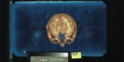
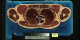
Here are some small jpeg images of a very few of the slices of the visible woman.
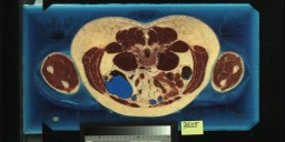
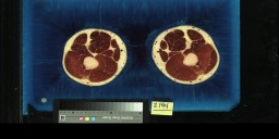
and
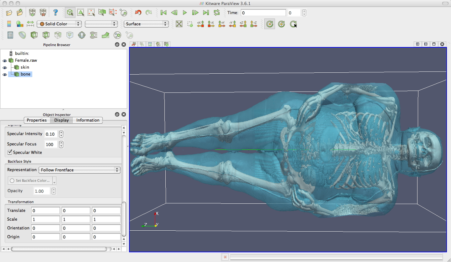
here is ParaView viewing the 75MB version of the Visible Woman dataset.
This version of the dataset is made up of 577 slices, 1 slide every
3mm, where each slice is 256 x 256 16-bit values. Once the
data is loaded in we can set up two contours - one for the skin and one
for the bones.
In
paraview
3.8.1
you
can
read
in
the
visible
woman data as raw
data then set:
and
then
create
two
contours of the Female.raw data
-
one
transparent aqua one at 850 for skin, and one
opaque white one at 1200 for bone, and you will see something similar
to this.
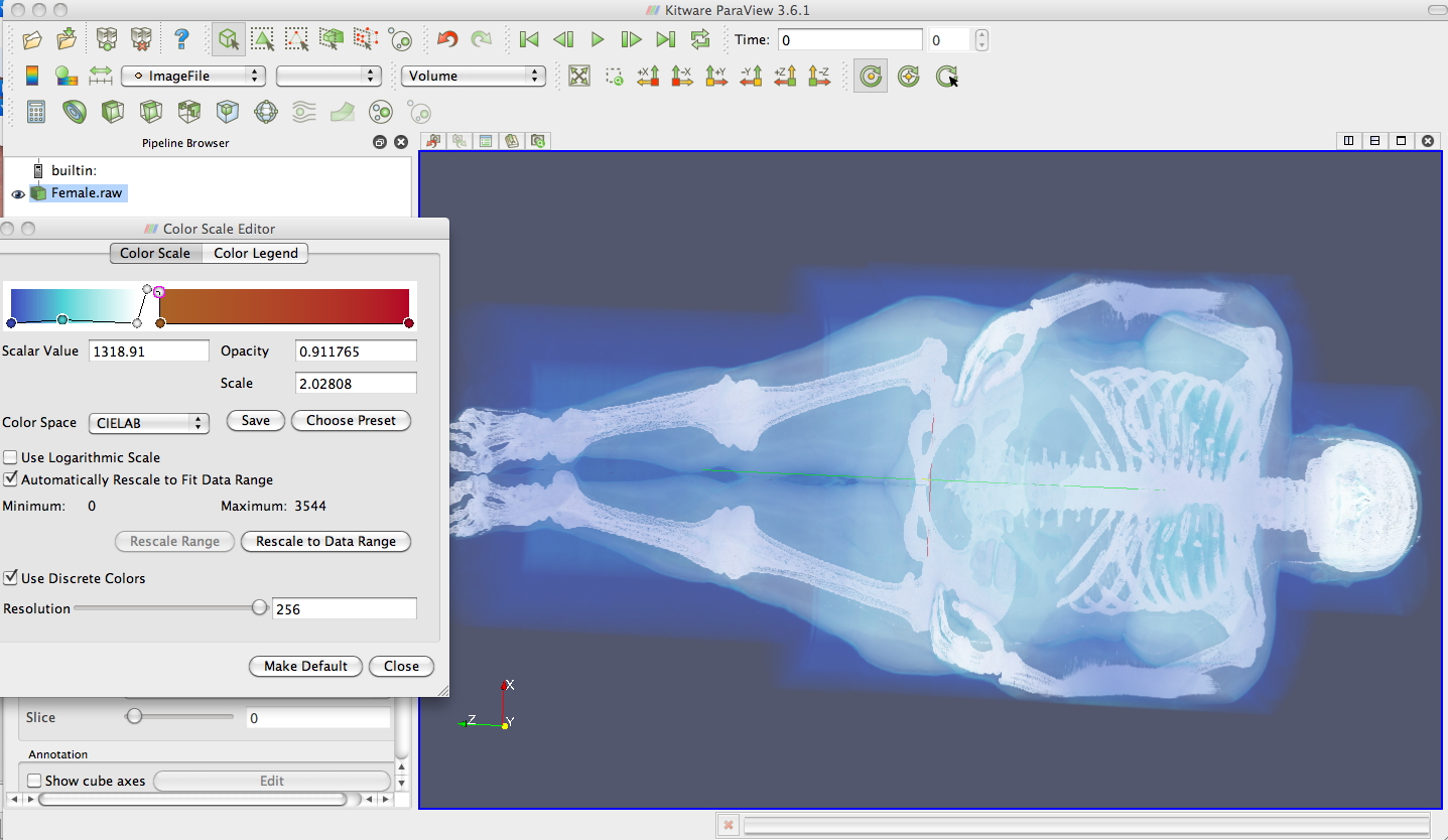
If
you think polygons are a little too 20th century then paraview can also
do some simple volume rendering
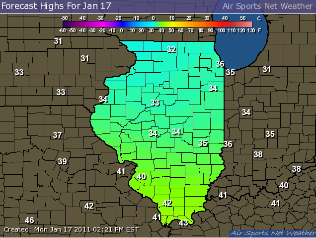
Discrete nature of data (Chap 5 vtk)
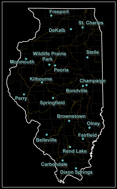
(possibly) continuous data represented by discrete samplingInterpolation
http://www.sws.uiuc.edu/warm/icnstationmap.asp
 |
 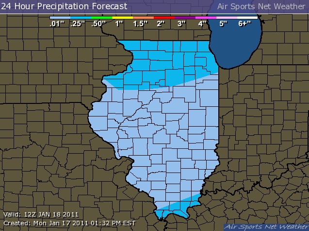 |
Here is another nice example of interpolating winds from the San Francisco Bay area
http://sfports.wr.usgs.gov/wind
In
particular, click on the 'Observed Wind over S.F. Bay' link to see the
observed data, then go back to the modelled data. Also click on the
streakline version to see the modelled data in motion.
Structured or Unstructured Data
Dimension (number of independent variables)
Abstract Dataset
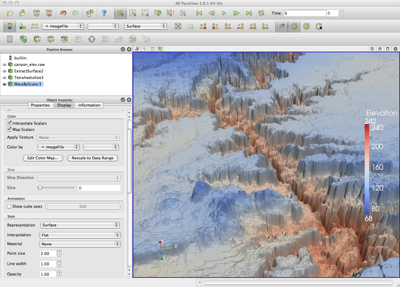
canyon_elev.raw
(which
can
be
found
at
ftp.evl.uic.edu
in
pub/INcoming/andy)
contains a
height map of the grand canyon as a 1024x512 greyscale image.
ParaView
can load this image by setting:
data type to 'unsigned char'
File Dimensionality to 2,
extents as 0-1023, 0-511
This will
bring up a colour image. You can use the information tab to bring up
information on the dataset. In this case that the values in the image
range from 68 to 242.
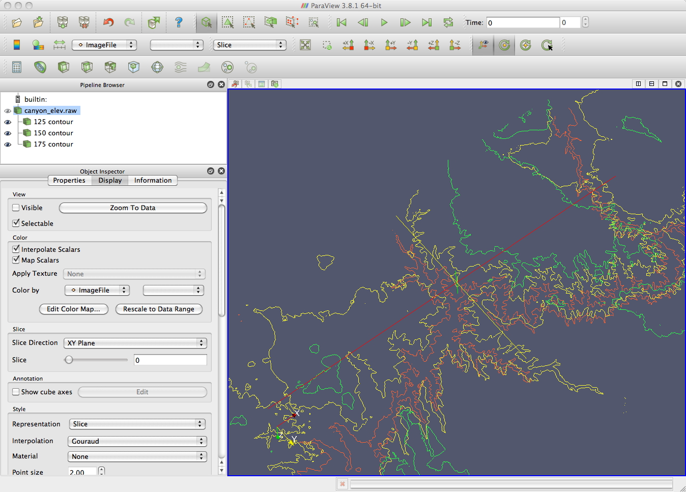
Then
you
can
use
the
Contour
filter
to
define
a series of contours. As the scalar values in the file
range from 68 to 242 you could set up a set of separate contours at
125,
150, and 175 for example. These contours would initially all be in the
same
plane, but you can also translate them in Z.
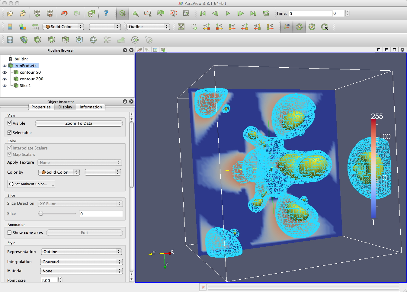
A dataset that comes with vtk is VTKData/Data is ironProt.vtk. Since it is a .vtk file, the header of this file contains the information that vtk needs to properly load the data in. Like the visible woman dataset we can use the contour tool to generate contours. In the image below there is a contour at 50 shown as wireframe, another contour at 200 shown as a surface, and a slice showing the data values in a plane (you need to Map Scalars in the Display tab for the contents of the plane to show up).
VTK
-
A
Programmer's
Perspective
Dennis created a page for setting up VTK / C++ / QT on Snow Leopard
Paul found this
page on
setting up vtk in visual studio 2008