Week 1
Into to the Course
Information about the Course - Syllabus,
presentations, projects etc.
How this class relates to to other similar / related
CS courses
CS 422
|
User Interface Design |
Focus on developing effective user interfaces
|
Every spring
|
CS 424
|
Visualization & Visual
Analytics
|
Focus on visualizing and
interacting with different kinds of large data sets
|
Every fall
|
CS 426
|
Video Game Programming |
Focus on creating complete audio visual interactive (and
fun) experiences |
Every spring
|
CS 488
|
Computer Graphics I |
Focus on the basics of how computers create images on
screens, OpenGL |
Every fall
|
CS 522
|
Human Computer Interaction |
Focus on interaction and evaluation of interactive
environments |
once every other year |
CS 523
|
Multi-Media Systems |
Focus on the creation of Educational Worlds |
once every other year
|
CS 524
|
Visualization & Visual
Analytics II
|
Focus on visualizing and
interacting with 3D data sets
|
once every other year
|
CS 525
|
GPU Programming |
Focus on shaders and parallel processing |
once every other year
|
CS 526
|
Computer Graphics II |
Focus on current trends in computer graphics
|
once every other year |
CS 527
|
Computer Animation |
Focus on creating realistic motion |
once every other year |
CS 528
|
Virtual Reality |
Focus on immersion |
once every other year |
Overview
1988 - Pixar creates Renderman (specification and the
renderer) for photorealistic off-line rendering including a
Shading Language. Renderman interface specification - intended to
formalize communication between modelling programs and rendering
programs. Renderman Shading Language allows arbitrary shaders to
be passed to the renderer by the interface.
At the same time, dedicated parallel processing
computers were being built (Connection Machine, MasPar, Cray) but
they were very expensive so the total number sold was in the
hundreds.
Late 90s - graphics cards now powerful enough for
real-time rendering with shading languages. Graphics cards are
focused on parallel processing in fixed areas, so they are
improving at a much faster rate than CPUs. Graphics card power is
doubling every 6 months. While designed for graphics work, many
computational problems can be re-cast in graphics terms and sped
up using these cards - your
data becomes a texture map, and your operation becomes an image
manipulation. This still results in the fastest computation, but
tools like Nvidia's CUDA allow programmers to take easier
advantage of particular cards with more general C-style coding.
Mid 00s - more general languages are developed to access
the power of the graphics cards, specific physics cards are
created as well as GPUs that are built only for computation.
early 10s - OpenCL language for writing code that can
run on a variety of platforms eg GPUs or CPUs from multiple
vendors. Microsoft has its similar DirectCompute as part of
DirectX 11. GPU capabilities being more tightly integrated into
CPUs.
Wikipedia has a nice overview of GPU and data on all of
the cards at http://en.wikipedia.org/wiki/Graphics_processing_unit
Several different languages currently out there - tend
to be very similar - all based on C/C++. Knowing one, it should be
very straight-forward to pick up one of the others.
- GLSL
- OpenGL Shading Language "g-l-slang"
- What we will mostly be talking about in this course
- HLSL
- High Level Shader Language for DirectX developed by
Microsoft
- Introduced in 2002 with DirectX 9
- HLSL compiles shaders into assembly language which is given
to DirectX
- Very similar to Cg
- Fairly similar to GLSL
- Cg
- Developed by nVidia
- Fairly similar to GLSL
- Cg translator can generate DirectX shader assembly code or
OpenGL shader assembly code mediated by Cg Runtime Library
This course will discuss
both graphical and general parallel computation. We will start
on the graphics side.
GLSL
Vertex Shaders
- transforms vertex information - runs once per vertex
Geometry
Shaders - Located after vertex shaders in the pipeline,
the geometry shader transforms primitive assembly information
(data on a single point, single line, single triangle) - runs once
per primitive
Fragment Shaders
(Pixel Shaders, Fragment Programs) - transforms fragment
information (data to update a pixel's colour in the frame buffer)
- runs once per fragment
lets take a brief look at the pipeline to see where
these fit in, then we'll come back to this in more detail later:
simple (older) pileline
http://www.lighthouse3d.com/tutorials/glsl-tutorial/pipeline-overview/
more modern pipeline
http://www.lighthouse3d.com/tutorials/glsl-core-tutorial/pipeline33/
Syntax is very
similar to C
- int, float, bool
- also have 2, 3, and 4 component vectors:
ivec{2,3,4}, vec{2,3,4}, bvec{2,3,4}
- also have square matrices: mat2, mat3, mat4
- and samplers for accessing texture values:
sampler{1,2,3}D, samplerCube
- if and if/else
- for loops, while loops
Shaders are sent
to the graphics driver as strings and then affect whatever is
drawn while they are active.
Really simple shaders:
vertex shader:
void main()
{
// needs to
write to gl_Position to output the vertex position in clipping
coordinates
gl_Position =
ftransform();
// which really: gl_Position
= gl_ModelViewProjectionMatrix * gl_Vertex;
// which is really: gl_Position =
gl_ProjectionMatrix * gl_ModelViewMatrix * gl_Vertex;
// caveat
// with starting with GLSL 1.4 the handy
ftransform function should no longer be used,
// though my examples will tend to use the
simpler earlier notation until I update them :)
// very likely
you will also want to set some colour, normal, light direction
values for
// this vertex as well so they will be
automatically interpolated in the fragment shader
}
With GLSL 1.4
the simplest vertex shader should look like the following:
#version 140
uniform Transformation {
mat4 projection_matrix;
mat4 modelview_matrix;
};
in vec3 vertex;
void main() {
gl_Position = projection_matrix *
modelview_matrix * vec4(vertex, 1.0);
}
which both
pass the vertex through
geometry
shader:
#version 120
#extension
GL_EXT_geometry_shader4 : enable
void main() {
for(int i
= 0; i < gl_VerticesIn; ++i) {
gl_FrontColor = gl_FrontColorIn[i];
gl_Position = gl_PositionIn[i];
EmitVertex();
}
EndPrimitive();
}
which passes
through each primitives set of vertices
fragment shader:
void main() {
//pass
through the colour set by glColorXX in OpenGL
//varying vec4 gl_Color;
//gl_FragColor = gl_Color;
// or instead
colour everything blue-ish
//gl_FragColor = vec4(0.4, 0.4, 0.8, 1.0);
}
A more realistic looking vertex
shader and fragment shader pair comes from chapter 6 of the Orange
Book. This shows additional information being passed from the main
program to the vertex shader and fragment shader, additional
information being passed from the vertex shader to the fragment
shader, and some of the nice functions you get for free.
vertex shader:
// Vertex shader for
procedural bricks
//
// Authors: Dave Baldwin,
Steve Koren, Randi Rost
//
based on a shader by Darwyn Peachey
//
// Copyright (c) 2002-2004
3Dlabs Inc. Ltd.
//
// See 3Dlabs-License.txt for
license information
//
uniform vec3 LightPosition; //
passed in from main program
const float
SpecularContribution = 0.3;
const float
DiffuseContribution = 1.0 - SpecularContribution;
varying float
LightIntensity; // passed from vertex to fragment shader
varying vec2
MCposition; // passed from vertex to fragment
shader
void main(void)
{
vec3
ecPosition = vec3 (gl_ModelViewMatrix * gl_Vertex);
vec3
tnorm = normalize(gl_NormalMatrix *
gl_Normal);
vec3
lightVec = normalize(LightPosition - ecPosition);
vec3
reflectVec = reflect(-lightVec, tnorm);
vec3
viewVec = normalize(-ecPosition);
float
diffuse = max(dot(lightVec, tnorm), 0.0);
float
spec = 0.0;
if (diffuse
> 0.0)
{
spec = max(dot(reflectVec, viewVec), 0.0);
spec = pow(spec, 16.0);
}
LightIntensity = DiffuseContribution * diffuse +
SpecularContribution * spec;
MCposition = gl_Vertex.xy;
gl_Position = ftransform();
}
fragment shader:
// Fragment shader for
procedural bricks
//
// Authors: Dave Baldwin,
Steve Koren, Randi Rost
//
based on a shader by Darwyn Peachey
//
// Copyright (c) 2002-2004
3Dlabs Inc. Ltd.
//
// See 3Dlabs-License.txt for
license information
//
uniform vec3 BrickColor,
MortarColor; //
passed in from main program
uniform vec2 BrickSize;
uniform vec2 BrickPct;
varying vec2
MCposition; // passed from vertex to fragment
shader
varying float
LightIntensity; // passed from vertex to fragment shader
void main(void)
{
vec3
color;
vec2
position, useBrick;
position =
MCposition / BrickSize;
if
(fract(position.y * 0.5) > 0.5)
position.x += 0.5;
position =
fract(position);
useBrick =
step(position, BrickPct);
color
= mix(MortarColor, BrickColor, useBrick.x * useBrick.y);
color *=
LightIntensity;
gl_FragColor = vec4 (color, 1.0);
}
which can be used to produce this brick texture procedurally:
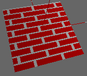
We will look at this code more in detail in lecture 3 - for now
you can see that in general it looks pretty similar to standard C.
In general shader code is very similar to C but the way you
approach a problem to take advantage of parallelism can be very
different from the code you have written before. Loops are rare in
shader code.
How do we make use of shader code in an OpenGL program? Here is
some OpenGL 2.1 code to set up a vertex and fragment shader,
whatever those shaders happen to be.
The shaders are written as
independent text files. OpenGL needs to load in and store the
shader source, then compile the source into executable code, and
then make it active. Like many things in OpenGL this is done
with handles.
GLuint setShaders(char * vert,
char * frag, char * geom) {
GLuint v,f, g, pro;
char *vs, *fs, *gs;
v = glCreateShader(GL_VERTEX_SHADER);
f = glCreateShader(GL_FRAGMENT_SHADER);
g = glCreateShader(GL_GEOMETRY_SHADER_EXT);
vs = textFileRead(vert);
fs = textFileRead(frag);
gs = textFileRead(geom);
const char * vv = vs;
const char * ff = fs;
const char * gg = gs;
glShaderSource(v, 1, &vv, NULL);
glShaderSource(f, 1, &ff, NULL);
glShaderSource(g, 1, &gg, NULL);
free(vs); free(fs); free(gs);
glCompileShader(v);
glCompileShader(f);
glCompileShader(g);
//fprintf(stderr, "vertex\n");
printShaderLog(v);
//fprintf(stderr, "fragment\n");
printShaderLog(f);
//fprintf(stderr, "geometry\n");
printShaderLog(g);
pro = glCreateProgram();
glAttachShader(pro,v);
glAttachShader(pro,f);
glAttachShader(pro,g);
// geometry shader details
// geometry shaders are different in that you
have to specify details about their input and output
// input: GL_POINTS, GL_LINES,
GL_LINES_ADJACENCY_EXT, GL_TRIANGLES, GL_TRIANGLES_ADJACENCY_EXT
// output: GL_POINTS, GL_LINE_STRIP,
GL_TRIANGLE_STRIP
glProgramParameteriEXT(pro,GL_GEOMETRY_INPUT_TYPE_EXT,GL_LINES);
glProgramParameteriEXT(pro,GL_GEOMETRY_OUTPUT_TYPE_EXT,GL_LINE_STRIP);
int temp;
glGetIntegerv(GL_MAX_GEOMETRY_OUTPUT_VERTICES_EXT,&temp);
glProgramParameteriEXT(pro,GL_GEOMETRY_VERTICES_OUT_EXT,temp);
glLinkProgram(pro);
printProgramLog(pro);
return(pro);
}
One of the main reasons that GPUs
are fast is because they can do the same small thing many times
at once in parallel. To harness this power the main program
needs to make data available to the card in a way that
encourages parallelism. For example, immediate mode with
begin/end and color changes interspersed with new vertices was
the primary way of writing OpenGL programs in the 90s, but today
that limits the amount of parallelism possible. The use of
DrawArrays on the other hand can help maximize parallelism as
large numbers of vertices, colours, and texture coordinates can
be sent to the card at once and then processed.
Here is a sample piece of code that shows the different ways of
coding - drawarrays.cpp
In the draw
loop we clear the buffers, set up the camera and lights, then call
glUseProgram(program); to install the
program as part of the current rendering state. We can then call a
function like glutSolidTeapot(1); and the teapot will be drawn
with the currently active set of shaders (though some shaders will
require additional input from the OpenGL code, as in the bricks
code above.)
You may very
likely have multiple sets of shaders and multiple Programs to hold
onto them so different parts of your scene can be drawn with
different shaders active.
Here are some links to the source code
and a fragment shader and a vertex shader and a Makefile (OS-X based) for a simple toon
shader, modified a bit from the lighthouse3d pages. This code
makes use of GLEW (the OpenGL Extension Wrangler)

Here are some links to a slightly more interesting version where
you can manipulate the teapot: source code, fragment shader, vertex shader, and Makefile.
To run these under Linux you will need to use the following Linux Makefile (assuming you put
glew into /usr/local) I tested this under Suse 10, but I think i
should be pretty generic.
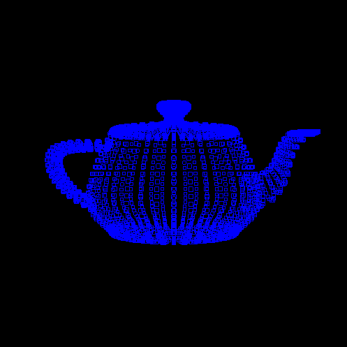
Here is the teapot run through a geometry shader where each vertex
is replaced by a wireframe square
main vert geom frag
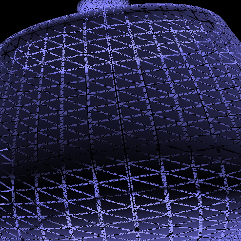
Here is another version of the
teapot where each of the triangles that makes up its surface are
shrinking
(adapted from
http://web.engr.oregonstate.edu/~mjb/cs519/Handouts/geometry_shader.pdf)
main vert geom frag
and I have
another one where the triangles are shrinking and moving away from
the center of the teapot but you really need to see that one in
motion.
main vert
geom frag
I was able to compile these under Windows XP using Visual C++ 6 by
making a command line project and adding glut.h, glut32.lib,
glut32.dll, GL/glew.h, glew32.lib, glew32.dll to the project
directory, and adding glew32.lib and glut32.lib to Object/library
modules inside visual studio.
Graphics Pipeline
http://www.lighthouse3d.com/opengl/glsl/index.php?pipeline
As in the general pipeline we start
with vertices in object-space and end up with correctly coloured
pixels in the frame buffer.
Vertices
may be specified in Immediate mode or in a display list or
vertex buffer, but for best performance you should consider
using a vertex buffer.
Vertex
Processor (transformation and lighting):
Vertex information (location,
colour, normal, texture coordinates) is transformed by the vertex
shader. It operates on individual vertices with no knowledge of
topology. At the end of this phase all attributes associated with
each vertex are completely determined.
- vertex transformation by modelview
and projection matrices
- normal transformation and
normalization
- texture coordinate generation and
transformation
- lighting per vertex or computing
values for lighting per pixel
- colour computation
Primitive
Assemby:
At this point each vertex is positioned relative to the
appropriate perspective or parallel canonical view volume. The
information coming out of the vertex processor is combined with
the connectivity information so primitives (point, line,
triangle) can be assembled. Once enough vertices come through to
form the primitive, it is passed on. Here is where a geometry
shader can alter the primitives by adding or removing vertices or
changing the primitive type. Then the primitive goes through
clipping against the view volume, perspective/parallel projection,
and back-face culling.
Rasterization:
Primitives
(points, lines, triangles) are decomposed into smaller units
(fragments) corresponding to pixels in the frame buffer.
A fragment has:
- window coordinates
- depth
- color
- texture coordinates
- normal
The per-vertex
information is used to determine these values, for example by
interpolating the known values (position, colour, etc) at the
vertices.
Fragment
Processor:
The
interpolated fragment information (interpolated colour and
texture coordinates) are used by the fragment shader to create
the final depth and colour of the fragment. Note that here is no
access to the frame buffer at this stage. Also note that you
can't change a pixel location at this point.
If you write a fragment shader you need to handle ALL the
following things if you want them. You can't replace only part of
the fixed functionality of the pipeline and assume you will get
the rest of the functionality automatically. You wont.
- computing
colours
and texture coordinates per pixel
- computing
normals
if you want lighting per pixel
- texture
access and application
- fog
computation
Frame Buffer Operations
The interpolated fragment locations and the fragment
depth and colour values are used to update the pixel's colour
value in the frame buffer. A pixel may be affected by 0 or more
fragments.
Note that the shader behaviour is only defined for RGBA
buffers, not color indexed ones.
The makefile and source code above
shows how I have been writing GLSL-based programs on the mac. I
used macports to install glew, and then do the rest of my work
on the command line.
There are several ways to
make use of GLSL; here are some notes from the last class on
setting up GLSL and using a simple shader on various platforms
Arun's notes from 2006 for Linux/Mac: http://www.evl.uic.edu/arao/cs594/sdlglsl.html
Don's notes from 2006 for windows: http://www.evl.uic.edu/eolmst1/GLSL/
Sujatha's notes from 2008 for mingw: http://www.geocities.com/sujatha_1psg/cs525/glslinstall.html
Coming Next Time
GLSL Language Study
last revision 1/18/10