(notes from
the lighthouse3d tutorial and the Orange book)
But
first lets back up a bit and talk about functions in shaders
some more
GLSL uses
call by value-return There are no
pointers - input
parameters will be copied into the function (no passing by
reference) - output
parameters will be copied back out of the function to the caller
- in
(implied) - copy in but dont copy back out, writable within the
function -
const (const in) - same as in, but not writable within the
function - out - copy
out, undefined at entry to the function - inout -
copy in and copy out
Lighting
Overview
(from the nice lighthouse3d people)
The
OpenGL application sends a color using the glColor function
The
vertex shader receives the color value in the attribute
gl_Color
The
vertex shader computes the front face and back face colors,
and stores them in gl_FrontColor, and gl_BackColor
respectively
The
fragment shader receives an interpolated color in the varying
variable gl_Color, depending on the orientation of the current
primitive, i.e. the interpolation is done using either the
gl_FrontColor or the gl_BackColor values.
The
fragment shader sets gl_FragColor based on the value of
gl_Color
From week 2 of class we have the following built-in varying
variables:
So what's with these SecondaryColors? We can compute
the colour at a vertex in 1 or 2 parts if we want. By default the
primary colour is computed from emissive, ambient, diffuse, and
specular. If there is a secondary colour then the primary colour
is computed from emissive, ambient, and diffuse while the
secondary colour has the specular component (to allow the specular
highlights to be applied seperately after texturing so they match
the colour of the light source.) For now we'll do without it to
keep things simple.
No Lights
pass the
per-vertex colour and the secondary colour along
if (secondaryColor)
gl_FrontSecondaryColor = gl_SecondaryColor;
gl_FrontColor = gl_Color;
There
is a bunch of code in the Orange Book (1st or 2nd Ed.) on how to
do lighting in Chapter 9, which is a very good reference for doing
things right, but I think its overly complex to start out with. So
instead we are going back to the nice lighthouse3d people and
looking at their lighting tutorial for directional lights with
GLSL.
http://www.lighthouse3d.com/tutorials/glsl-tutorial/lighting/
Fog
Fog is used to simulate
atmospheric effects that make objects appear less distinct the
further they are away from the camera. Its often used in
combination with the far clipping plane to hide far away
objects popping in and out of the scene. OpenGL fog has an RGB
colour which typically matches the background colour. The fog
colour is used to modify the final colour of objects with
several different possible equations for how the object colour
and for colour are mixed (linear,
exponential, more exponential.)With linear fog the fog
starts (fog=0%) at a given distance from the camera, ends
(fog=100%) at a further distance from the camera, with linear
mapping in between. With exponential fog a fog density is used
along with the distance
From week 2 of class we have the following built-in varying
variable:
varying float gl_FogFragCoord;
attribute float gl_FogCoord; // vertex attribute like gl_Normal or
gl_Vertex
in the simple case the vertex shader will do
gl_FogFragCoord = gl_FogCoord;
Typically
compute
in the vertex shader and then pass to the fragment shader since
its faster but you could compute fog in the fragment shader
fog = (gl_Fog.end -
gl_FogFragCoord) * gl_Fog.scale; // linear
fog = exp2(-gl_Fog.density *
gl_FogFragCoord * 1.442695); // exponential
fog = exp2(-gl_Fog.density *
gl_FogDensity
* gl_FogFragCoord
* gl_FogFragCoord * 1.442695); // more exponential
where
gl_Fog.scale is 1.0 / (gl_Fog.end - gl_Fog.start)
then clamp with
fog = clamp( fog, 0.0, 1.0);
then in the
fragment shader
color = mix(vec3
(gl_Fog.color), color, fog);
Textures
Texture Access Functions: vec4 texture2D(sampler2D sampler, vec2 coord)
use coord to do a lookup into the texture currently specified by
the sampler
A typical 2D texture is created or
leaded into the program with a certain number of pixels in
either dimension. For better speed its highly suggested that the
texture be square and have the number of pixels in each
dimension be a power of 2 (e.g. 16, 32, 64, 128, 256, 512, 1024,
etc) so a nice texture size is 512 x 512 or 1024 x 1024.
Internally the texture is indexed by (s, t) values which range
from 0.0 to 1.0 allowing textures with different numbers of
pixels to use the same coordinate system.
When we specify the vertex of a
polygon we can give that vertex a location, a normal vector, a
color, and a texture coordinate. In the example below we are in
immediate mode specifying the values in turn. As we saw back in
week 1 the more modern way makes use of arrays of vertices,
colours, textures.
in the application program:
for example we could initialize a given texture with the following
function:
GLuint textureNum[1];
// space to hold one texture name
glGenTextures(1, textureNum); // generate one unique texture
name
//
create
new 2D texture and give it the unique name generated above
// more info on all this in chapter 9 (Texture
Mapping) of the red book
glBindTexture(GL_TEXTURE_2D, textureNum[0]);
// define
a new texture - lots of possible parameter values here // here
are a couple typical ones: greyscale and rgb // // 2D
texture // not
doing multi-resolution so level=0 //
internal format = 1 (GL_LUMINANCE) only one value per texel // width
and height both = 64 // no
border so border = 0 // format
= GL_LUMINANCE // type =
unsigned byte //
pointer to where the texture data was stored after being read in
glTexImage2D(GL_TEXTURE_2D, 0, 1, 64, 64, 0, GL_LUMINANCE,
GL_UNSIGNED_BYTE, (const GLvoid *) texData);
// or a
512 by 512 rgb texture
//glTexImage2D(GL_TEXTURE_2D, 0, GL_RGB, 512, 512, 0, GL_RGB, //
GL_UNSIGNED_BYTE, (const GLvoid *) texData);
// if we
give s,t values outside the 0-1 bounds we want to wrap around
glTexParameterf(GL_TEXTURE_2D, GL_TEXTURE_WRAP_S, GL_REPEAT);
glTexParameterf(GL_TEXTURE_2D, GL_TEXTURE_WRAP_T, GL_REPEAT);
// how do
we deal with interpolation
glTexParameterf(GL_TEXTURE_2D, GL_TEXTURE_MAG_FILTER,
GL_LINEAR);
glTexParameterf(GL_TEXTURE_2D, GL_TEXTURE_MIN_FILTER,
GL_LINEAR);
// and
then save off the texture name so we can use it later texStore
= textureNum[0];
and then we could draw the polygon to be texture mapped as normal:
glBegin(
GL_POLYGON );
// set the s and t texture coordinates for this
vertex
glTexCoord2f( 1.0f, 1.0f );
// we could also set a colour and/or a normal
for this vertex
// and here is the vertex
glVertex3f( -2.0f,
-2.0f, 0.0f);
// now we set up the information for the next
vertex
glTexCoord2f( 0.0f, 1.0f );
glVertex3f( 2.0f, -2.0f, 0.0f);
// and the third vertex
glTexCoord2f( 0.0f, 0.0f
);
glVertex3f( 2.0f, 2.0f, 0.0f);
// and the fourth vertex
glTexCoord2f( 1.0f, 0.0f );
glVertex3f( -2.0f, 2.0f, 0.0f);
glEnd();
we need two
uniform variables - light position for vertex shader and texture
unit for fragment shader. This should look similar to the
procedural brick example that we went through last week.
GLint texLoc, lightLoc;
texLoc = glGetUniformLocation(programObj, "textureName");
glUniform1i(texLoc, 0); // 0 because first texture is number 0,
second is 1, third is 2, etc
// get
the texture coordinates from the OpenGL program and // store
it in the varying variable TexCoord for the fragment shader
// current versions of glsl have the built in
varying variable gl_TexCoord[i]
// so you could also write
gl_TexCoord[0] = gl_MultiTexCoord0; TexCoord = gl_MultiTexCoord0.st;
gl_Position = ftransform(); }
void main(void)
{
// use the interpolated s and t values to grab
the colour
// from the appropriate location in the texture
// the more modern usage with gl_TexCoord[0] would be
// vec3 texColor
= vec3 (texture2D (textureName, TexCoord[0].st)); vec3 texColor = vec3
(texture2D (textureName, TexCoord.st));
gl_FragColor = vec4 (texColor *
LightIntensity, 1.0);
}
note that
this is a very simple case where we are using the colour of the
texture and the light intensity to give the final colour. We are
not trying to blend the texture with the colour of the underlying
fragment.
in an even simpler case we could just assign the colour of the
fragment to be the colour of the texture at that location and
ignore the light: gl_FragColor = vec4 (texColor, 1.0); we can also
try to blend the texture colour with the underlying primitive
colour which is affected by the light: void main(void)
{ vec4
texel = texture2D (textureName, TexCoord.st);
vec3 texColor = texel.rgb;
float texAlpha = texel.a;
we could also
play with the channels of the texture - i.e. showing only the red
component: gl_FragColor
= vec4 (texColor.r, 0.0, 0.0, 1.0);
Here you are doing what OpenGL will do automatically for
you with GL_REPLACE and GL_MODULATE. As above with the lighting
it gives you a better idea what is going on behind the scenes
and why some settings in OpenGL take longer to render than
others. Multitexturing
Its pretty simple using GLSL to combine two textures together. The
fragment shader needs a new sampler for the second texture:
uniform sampler2D textureName0,
textureName1;
if we use
the same texture coordinates for both textures then we can do the
following, which shows the red channel of the first texture in red
combined with showing the red channel of the second texture in
blue: vec3 texColor0 = vec3 (texture2D
(textureName0, TexCoord.st));
vec3 texColor1 = vec3 (texture2D (textureName1, TexCoord.st));
otherwise we would need specific texture coordinates for the
second texture. In this case we would need the vertex shader to
set two varying variables - one to hold s and t values for the
first texture, and another to hold s and t values for the second
texture. varying vec2 TexCoord0, TexCoord1; TexCoord0 =
gl_MultiTexCoord0.st; TexCoord1 = gl_MultiTexCoord1.st;
and then the
fragment shader can do:
vec4 texel = texture2D (textureName0,
TexCoord0.st) + texture2D (textureName1, TexCoord1.st);
The syntax for this is changing again in version 140, so if you
look in the 3rd edition of the Orange Book in chapter 10 you will
see some slightly different code.
You could also dynamically change the blending of the textures
based on say time, or lighting. This allows you to do simple
animations.
The Day/Night Earth example from Chapter 10 of either the 1st or
2nd editions of the Orange Book is another good example. Environment Mapping
Modelling reflections in a complex environment without 'doing it
right' using ray-tracing
Take a single texture map covering 360 degrees horizontal and 180
degrees vertical or 6 textures forming a cube map.
For a single texture map we use the reflection vector from an
object's surface (converted to altitude and azimuth) to get colour
from the spherical environment map. In this case we are generating
the texture coordinates from within the fragment shader for each
fragment.
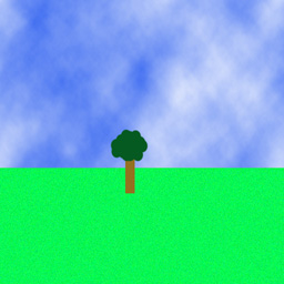
We could start with a simple spherical environment map like this
in the Application Program:
set up the uniform variables:
LightPos - vec3 - location of the light source
in eye coordinates
BaseColor
-
vec3
-
base
colour
of
the
object
MixRatio
-
float
-
ratio
of
base
colour
to environment map reflection
envMap - sampler2D - which texture unit the environment
map is stored in
in the Vertex Shader
// Vertex shader for
environment mapping with an // equirectangular 2D texture // Authors: John Kessenich,
Randi Rost // Copyright (c) 2002-2004
3Dlabs Inc. Ltd. // See 3Dlabs-License.txt for
license information
varying vec3 Normal;
// surface normal in
eye coordinates varying vec3 EyeDir;
// eye direction ==
loc of vertex in eye coordinates
// (the eye is at 0,0,0 in
canonical view volumes) varying float LightIntensity;
// diffuse light
// Fragment shader for
environment mapping with an // equirectangular 2D texture // Authors: John Kessenich,
Randi Rost // Copyright (c) 2002-2004
3Dlabs Inc. Ltd. // See 3Dlabs-License.txt for
license information
// index.x
ranges from -0.5 to 0.5 // index.y
ranges from -1 to 1 // texture
coordinates range from 0 to 1 in both dimensions (aside from
wrapping)
//
Translate index values into proper range // t
(elevation) value is straight forward, s (azimuth) is a bit more
complicated // if
reflectDir.z >= 0.0, s will range from 0.25 to 0.75 (front side)
// if reflectDir.z < 0.0, s will range
from 0.75 to 1.25 (-0.25) (back side)
//
which
is
OK
since
we are wrapping
// t will range from 0 to 1
if
(reflectDir.z >= 0.0) // reflecting towards the front
index = (index + 1.0) * 0.5;
else
//
reflecting towards the back
{
index.s = (-index.s) * 0.5 + 1.0;
index.t = (index.t + 1.0) *
0.5; // same as for index.t above
}
// Do a lookup into the environment map
vec3 envColor = vec3 (texture2D(envMap,
index));
// Add lighting to base colour and mix
vec3 base = LightIntensity * BaseColor;
envColor = mix(envColor, base, MixRatio);
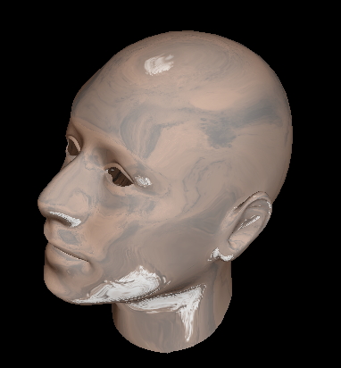
One could also use this kind of simple environment map on a more
complex shape like this .obj file of my head that now has mars
reflected on it:
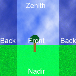
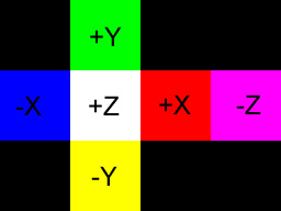
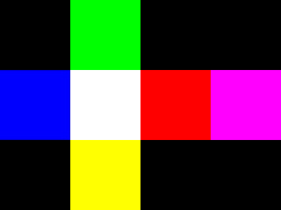
For a cube map we have the following set of planes defining the
environment map:
So for example we could have the following simple set of 6
textures forming a cube map where each texture is a solid colour.
In this case they are 64 by 64 pixels.
you would then use vec4 textureCube
(samplerCube sampler, vec3 coord) to do the lookup and the code
simplifies quite a bit to the following:
you could also do refraction as
well as reflection as discussed in chapter 14 of the
2nd edition. In this case we not only complute a reflection
vector bouncing off the surface of the object but also a
refraction vector that goes through the object. For more on
refraction you can see: http://en.wikipedia.org/wiki/Index_of_refraction
vertex shader
// from the Orange Book 2nd
edition
const float Eta = 0.66; const float FresnelPower =
0.5; const float F =
((1.0-Eta)*(1.0-Eta))/((1.0+Eta)*(1.0+Eta));
vec3 color = mix(refractColor,
reflectColor, Ratio);
gl_FragColor = vec4(color,
1.0); }
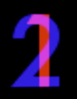
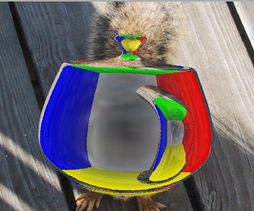
here is an example with refraction
turned on and the background, which was purple in the previous
example, set to the squirrel photo we will use next week.
and to be even fancier you can use
different values of Eta for the R, G, and B components to get
chromatic aberration - those colour fringes you see on cheap
wide angle camera lenses - for example for a glass/air
transition the values are R: 0.65, G: 0.67, and B: 0.69 with
more info at http://en.wikipedia.org/wiki/Chromatic_aberration
here is a gzipped tar file
containing all the parts for that.
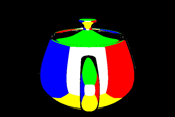
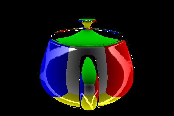
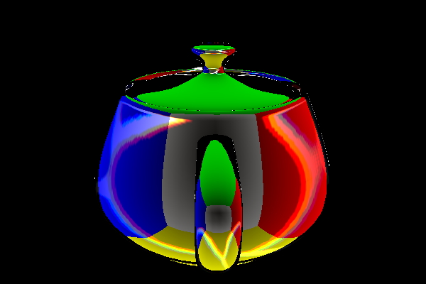
its hard to
see chromatic aberration with the squirrel background, but with
a white circle on a black background it becomes much more
obvious. Below there is the reflecting teapot, a reflecting and
refracting teapot without chromatic aberration, and finally a
reflecting and refracting teapot with chromatic aberration.
Procedural Textures (e.g.
the brick example we did before)
have
low memory requirements
have no
fixed resolution
can be
parameterized
but
may be
hard to program
can be
slow depending on the algorithm
suffer
from aliasing (unless you use a more sophisticated/slower
algorithm)
May also have
combinations of different texturing on the same object
Bump Mapping
modulating the surface normal before applying
lighting
adds apparent geometric complexity during fragment processing
lighting will be done in the fragment shader
need normal, light source direction, and
viewing direction for each fragment
going to use surface local coordinate space
(tangent space)
the point we are working on is defined as (0,
0, 0) and unperturbed normal is (0, 0, 1)
then we have:
- X axis - tangent vector -
{1.0, 0.0, 0.0}
- Z axis - normal vector -
{0.0, 0.0, 1.0}
-
Y
axis
-
binormal
vector
-
{0.0,
1.0, 0.0} derived from tangent and normal vectors
Which means we now need to convert the light
from eye/camera space to tangent space
x = light dot t
y = light dot b
z = light dot n
but before we can do that we need to get t, b,
and n.
We have N. We need to pass
in a tangent vector as an attribute variable, then we can do:
vec3 n = normalize(gl_NormalMatrix *
gl_Normal);
vec3 t = normalize(gl_NormalMatrix * Tangent);
vec3 b = cross(n, t);
A good discussion can be found at: http://www.ozone3d.net/tutorials/bump_mapping.php
along with vertex and fragment shader code.
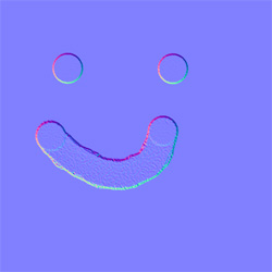
A normal map is a texture map where
each element contains an XYZ normal vector instead of an RGB
colour. A given polygon has a texture map to give the
surface colour, and a normal map to give the surface roughness.,
this way light will appear to reflect off a rough (more
interesting and detailed) surface rather than a smooth polygonal
surface.
These normal vectors are given in tangent space. Since a texture
map can only hold positive values, we need a way to encode
negative values, so normals that range from -1 to 1 are
represented by texels that range from 0 to 1. A normal map
that does nothing would have normals of (0.0, 0.0, 1.0) and
to represent that each texel would contain (0.5, 0.5, 1.0) as
shown below. We take the normal data, add 1, and divide by
2. Since the normal maps tend to have strong Z values they will
tend to be light bluish.
So lets say
we have the following normal map. There are various freeware
programs out there that will create normal maps from common
image formats.
in the vertex
shader
// Vertex shader for
procedural bumps // Authors: Randi Rost, John
Kessenich // Copyright (c) 2002-2005
3Dlabs Inc. Ltd. // See 3Dlabs-License.txt for
license information
// convert
normal and tangent (from main program) into eye space vec3 n =
normalize(gl_NormalMatrix * gl_Normal); vec3 t =
normalize(gl_NormalMatrix * Tangent);
//
compute b in eye space
vec3 b = cross(n, t);
// convert
light direction from eye space to tangent space vec3 v; v.x =
dot(LightPosition, t); v.y =
dot(LightPosition, b); v.z =
dot(LightPosition, n); LightDir =
normalize(v);
// convert
eye direction from eye space to tangent space v.x =
dot(EyeDir, t); v.y =
dot(EyeDir, b); v.z =
dot(EyeDir, n); EyeDir =
normalize(v); }
in the
fragment shader
// Fragment shader for
procedural bumps // Authors: Randi Rost, John
Kessenich // Copyright (c) 2002-2005
3Dlabs Inc. Ltd. // See 3Dlabs-License.txt for
license information // tweaked a bunch by
Andy
varying vec3 LightDir; //
interpolated in tangent space varying vec3 EyeDir; //
interpolated in tangent space
varying vec2 TexCoord; // interpolated across the normal map
vec3 SurfaceColor = vec3(0.7,
0.6, 0.18); // golden colour for the surface float SpecularFactor = 0.5;
uniform sampler2D normalName;
// sampler for the normal map
void main (void) { vec3
litColor;
// use the interpolated TexCoord to read the
normal from the normal map
vec3 normDelta = vec3 (texture2D (normalName,
TexCoord.st));
// convert
the normal from 0.0 - 1.0 to -1.0 - 1.0 normDelta
*= 2.0; normDelta
-= 1.0;
// use this new normal to work out the diffuse
lighting component
litColor = SurfaceColor * max(dot(normDelta,
LightDir), 0.0); vec3
reflectDir = reflect(LightDir, normDelta);
// use this new normal to work out the specular
lighting component float spec
= max(dot(EyeDir, reflectDir), 0.0); spec =
pow(spec, 6.0); spec *=
SpecularFactor;
So now lets
try a procedural bump map from chapter 11 of
the Orange Book.
the vertex shader is the same
in
the fragment shader
unlike the previous example, in this case the 'bumps' are not
coming from a normal map, but are being computed in the fragment
shader based on a bump density and a bump size, so its simular to
the way we consturcted the procedural bricks as a texture, except
this time we are constructing procedural bumps in the surface.
// Fragment shader for
procedural bumps
// Authors: Randi Rost, John Kessenich
// Copyright (c) 2002-2005 3Dlabs Inc. Ltd.
// See 3Dlabs-License.txt for license information
// tweaked a bit by Andy to remove the uniform variables
varying vec3 LightDir;
varying vec3 EyeDir; varying vec2 TexCoord;
vec3 SurfaceColor =
vec3(0.7, 0.6, 0.18); float BumpDensity = 16.0;
// how many bumps in a row or column float
BumpSize = 0.15; // how big each individual
bump is float SpecularFactor =
0.5;
void main (void)
{ vec3
litColor; vec2 c
= BumpDensity * TexCoord.st; // bump number - c ranges from
0 to 16 in this case vec2 p
= fract(c) - vec2 (0.5); // angle of normal changing over the
bump area
// p
ranges from -0.5 to 0.5 for each bump, bump centered at 0.0
float
d, f; d =
p.x * p.x + p.y * p.y; // d is the 'radius' of this
fragment from center of its bump f =
1.0 / sqrt(d + 1.0); // f normalizes length of the normal:
sqrt(x^2 + y^2 + z^2)
// if we are outside the spherical area of a
bump then normal points straight out Z w/ length 1 if (d
>= BumpSize)
{
p = vec2(0.0);
f = 1.0;
}
// create a new normal of length 1 for this
fragment vec3
normDelta = vec3 (p.x, p.y, 1.0) * f;
Here is some
sample code for bump mapping: application,
vertex shader, fragment shader
and here is the gzipped tar
file Noise
can't be random since we need to repeatedly
produce the same pattern each frame
ideally:
continuous
repeatable
well
defined output range
does
not show regular patterns
isotropic
(rotationally
invariant)
can be
defined for different dimensions
creating a
noise texture (chapter 15 of the Orange Book 2nd ed)
GLSL has (will have) a built-in
noise function that you can use, as in the code below, once
various card makers get around to actually implementing it,
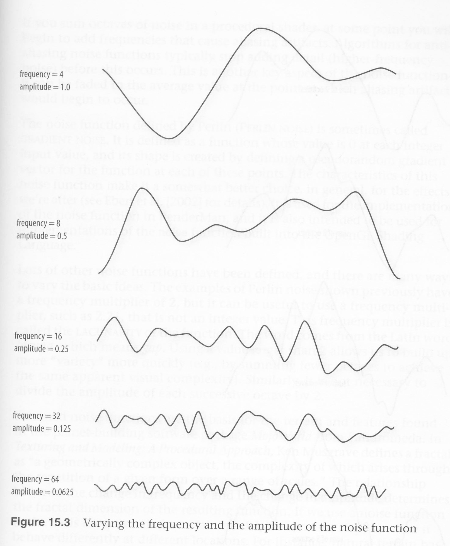
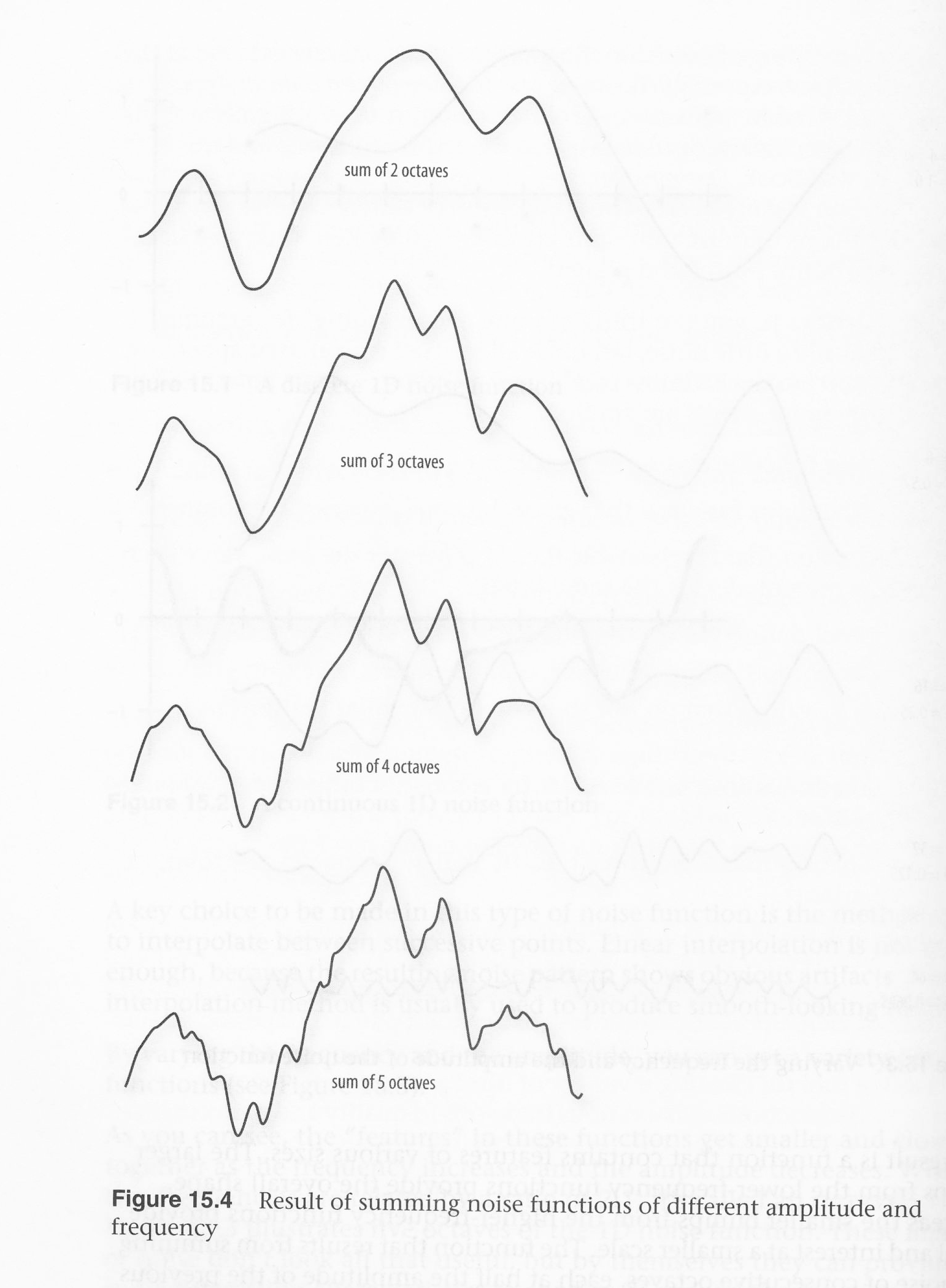
until then you need to make your own. The main idea here is to
generate noise with courser and finer features that can be added
together to create more realistic noise.
Given a
starting (course) frequency and amplitude, we create multiple
(finer) octaves by doubling the frequency and halving the
amplitude in the OpenGL program. We do this once at the
beginning of the program execution and store the values in a 3D
texture map. The fragment shader can then combine these
different levels of noise in different ways to create different
materials.
The orange book has some nice figures in chapter 15.
int noise3DTexSize = 128; GLuint noise3DTexName = 0; GLubyte *noise3DTexPtr;
void make3DNoiseTexture(void) { int f, i,
j, k, inc; int
startFrequency = 4; int
numOctaves = 4; double
ni[3]; double
inci, incj, inck; int
frequency = startFrequency; GLubyte
*ptr; double amp
= 0.5;
// allocate
space for 4 octaves each of size 128 by 128 if
((noise3DTexPtr = (GLubyte *) malloc(noise3DTexSize *
noise3DTexSize *
noise3DTexSize * 4)) ==
NULL)
{
fprintf(stderr, "ERROR:
Could not allocate 3D noise texture\n");
exit(1);
}
// Generate each octave in turn
for (f=0, inc=0; f < numOctaves;
++f, frequency *= 2, ++inc, amp
*= 0.5)
{ SetNoiseFrequency(frequency);
ptr = noise3DTexPtr;
ni[0] = ni[1] = ni[2] = 0;
inci = 1.0 / (noise3DTexSize
/ frequency);
for (i=0;
i<noise3DTexSize; ++i, ni[0] += inci)
{
incj =
1.0 / (noise3DTexSize / frequency);
for (j=0;
j<noise3DTexSize; ++j, ni[1] += incj)
{
inck = 1.0 / (noise3DTexSize / frequency);
for (k=0; k<noise3DTexSize; ++k, ni[2] += inck, ptr+= 4)
{
*(ptr+inc) = (GLubyte) (((noise3(ni)+1.0) *
amp)*128.0);
}
}
}
} }
We want a noise function that has
features of various sizes and that can be used for multiple types
of noise. We are going to store the noise in a 3D texture where
each texel contains different octaves in the r, g, b, and a
components (each component having twice the frequency and half the
amplitude compared to the one before it.)
and, one last link ... there is a nice image here on some of the
different effects that are possible: http://www.noisemachine.com/talk1/19.html
in the vertex shader - clouds: