Character Building Process for Project “Last
Drop!”
Skeleton and Inverse Kinematics
(IK handles) Setup
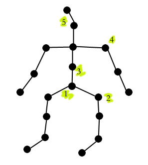
Setting joints:
- Start joint setup from pelvis (root joint) then proceed down to ankle joints.
- Then branch off for the other leg, once again starting from the pelvis joint.
- Move up from pelvis joint to create the back bone, ending it with collar joint.
- From collar joint, create an arm skeleton (forming joints down to wrist joint L/R).
- Finally, move from collar joint up forming the neck and head joints.
Setting “rest
pose”:
- Select a joint or top node for the whole skeleton.
- Go to “Edit” à set rest pose.
- To assume rest pose, go to “Edit” à assume rest pose.
Adding IK (inverse
kinematics) Handles:
- With nothing pick, select “Add IK Handle”. Click “root” (pelvis) and “end effector” (ankle).
- Create two IK Handle, one for the leg and the other for the ankle.
- Test the motion by “pick IK Handle” and xform (move).
Setting
constraints to IK Handles:
- Pick the two IK Handles and go to “Windows” à “Edit” à Skeletons.
- Set “list type” à handles and activate use limit to X rotate for the “knee joint” of leg portion.
Add Selection
Handles (optional):
- Select either IK Handle or joint.
- Go to “Edit” à new selection handle then xform it out of skeleton for clarity.
Head Node Creation
Set
- Group “Full_head”, eye (L&R), ear (L&R) with pivot point in the center of group.
- Rotate head on y axis to face it forward then rotate to face it forward and then move it to match old “head” surface. (Do not “freeze transformation” or delete “history”.)
- Change the pivot point of new head group to below back of head and then rename the group node.
- Relocate all the “control” nodes (ear, mouth, eye) to the desired locations.
- Delete old “head” surface (sphere) and create a single joint with “orientation” to none.
- Connect the new joint to “joint16” and rename new joint to “head_joint” (this would be the head control).
- Parent the new head group geometry to “head_joint” and the same for the rest of the “control” nodes.
- Test the result with keyframing of the “body”.
Soft Body Dynamics
Setup
“Freeze Transformation” of the torso
geometry, then proceed accordingly.
1.
Create a lattice for the torso (body) with the
following inputs: [s]à 2, [t] à 6, and [u] à 3. Make sure the option “parent lattice to
selection” is checked.
2.
Bind lattice to joint13 or “pelvis joint” with “color
joints, complete skeleton” as activated options (select just lattice, not “torso” geometry).
3.
Select just torso geometry and go to “Bodies” à soft
bodies. In the option box, select “Duplicate,
Make Copy Soft” and a weight of 1.
Engage “Hide Non-Soft Object” and “Make Non-Soft A Goal”.
4.
At this point, create the blend surfaces for any
surfaces that will be attached to the torso (i.e. neck, legs, and arms).
5.
Select the “copy” of torso (soft body) and open “Attribute
Editor” window. Go to “Copy of
torsoParticlesShape” tab and locate the “Per Particle (Array) Attributes”.
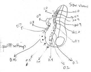
6.
Right mouse click on “goalPP” section and select “Component
Editor”.
7.
Select the particles to edit goal weight on a per
particle basis (this will affect which section of the torso will “jiggle” more
or less).
8.
Select “copy” of torso then go to “Fields” à create
gravity. Link the gravity to the “copy”
of torso via “Dynamics Relationship” window.
Finally, add “Springs”.
9.
Set up a particle disk cache for testing
purposes. Select “copy” of torso and in
the “Channel Box”, make sure “set cache data” is on and “enable scene
cache”.