Transparently supporting a wide range of VR and stereoscopic display devices
Dave Pape, Dan Sandin, Tom DeFanti
Electronic Visualization Laboratory, University of Illinois at Chicago
Abstract
This paper describes an architecture for virtual reality software which transparently supports a number of physical display systems and stereoscopic methods. Accurate, viewer-centered perspective projections are calculated, and graphics display options are set, automatically, independent of application code. The design is intended to allow greater portability of applications between different VR (and other) devices.
Introduction
Virtual reality is proving useful in a variety of fields, including science, engineering, art, and entertainment. However, there is not a standardized base for all these applications - there are many, widely varying hardware systems. All these systems have software to drive them, but often this software is device specific; if someone develops an application for one VR display, they might only be able to use it on that specific type of hardware. This is contrary to the needs of many VR users. Scientists want to have tools that they can share with collaborators at other institutions, which might have different hardware; artists want to be able to show their work widely, without being limited to a handful of sites with a certain brand of display.
In our own lab's work, we have created a wide variety of applications for the CAVE and related systems ([1], [2]); in order that applications not be restricted to a few systems, we have focused on building an open, flexible architecture for VR device support. Our software architecture has evolved through experiments with several display technologies. It was originally created to support CAVE systems and was later expanded to also support the ImmersaDesk and other internal, experimental systems. Because of our work with other groups, we also handle head-coupled (HMD, BOOM) displays. In addition to different geometries, these systems sometimes make use of distinctly different methods of displaying stereo image pairs from graphics workstations.
We describe a unified system for rendering viewer-centered, stereoscopic images for arbitrary display devices. We focus on two major aspects - computing the viewing transformations for accurate perspective projections, and handling the rendering details of different stereo display methods. The architecture described automates these details and uses run-time configuration, so that everything is transparent to application code.
Background
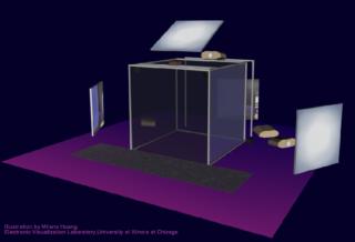
Our system was first developed for the CAVE projection-based VR display ([3]). The CAVE consists of several large screens which surround the viewer (Figure 1); stereoscopic images are projected on the screens, and the viewer's head position is tracked. The original design, as described in [3], was driven by several Silicon Graphics deskside workstations - one per screen. Later implementations have used larger machines with multiple graphics pipes, so that a single machine can run an entire CAVE. Sometimes there are multiple video channels per pipe, allowing one pipe to drive two (or more) walls. For the illusion of immersion to be successful in a system such as this, the multiple screens need to appear seamless, as if they formed a single screen surrounding the viewer. Part of this is accomplished in the physical design, by minimizing the physical seams between screens, and color-matching and electronically aligning the projectors. But, it is also important to render the images for the different screens accurately and seamlessly. Correct viewer-centered perspective projections must be used, so that the image rendered for each screen corresponds to the viewing volume defined by the eye-point and the edges of the screen (Figure 2). Also, all of the rendering needs to be synchronized, so that the different projections are computed from the same tracked data, and the screens are updated simultaneously.
Figure 1. The CAVE
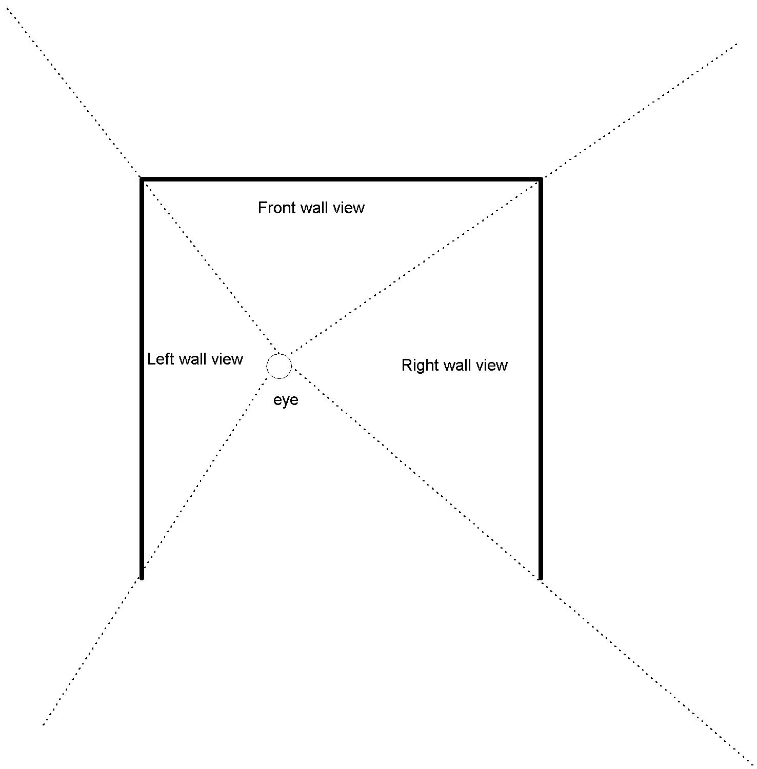
Figure 2. Overhead view of CAVE viewing volumes
The geometry of the CAVE is fairly straightforward - the screens are axis-aligned faces of a cube - making some simplifications in the projection calculation possible. However, later systems, such as the ImmersaDesk (Figure 3), Infinity Wall, and current research projects ([4], [5]), are not so simple, and require one to consider screens which can have any arbitrary position and orientation in space. Furthermore, in systems such as the ImmersaDesk3 and CAVEscope ([5]), the screens can move, independently of the viewer.
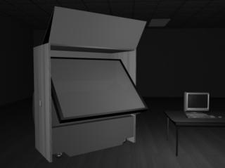
Figure 3. The ImmersaDesk
Perspective Projection
In general, the projection problem, whether it be for a CAVE, HMD, or other display, reduces to an eye point viewing the scene through an arbitrary rectangular image plane - the display screen (Figure 4). We assume the image plane is a flat, undistorted rectangle because that is the case for CAVE and related projection based systems, and because that is the model which OpenGL and the rendering hardware support. HMDs and curved screen projection systems have varying degrees of image distortion, but this must be dealt with at a separate stage in the rendering, and so for the projection calculation we treat them as undistorted.
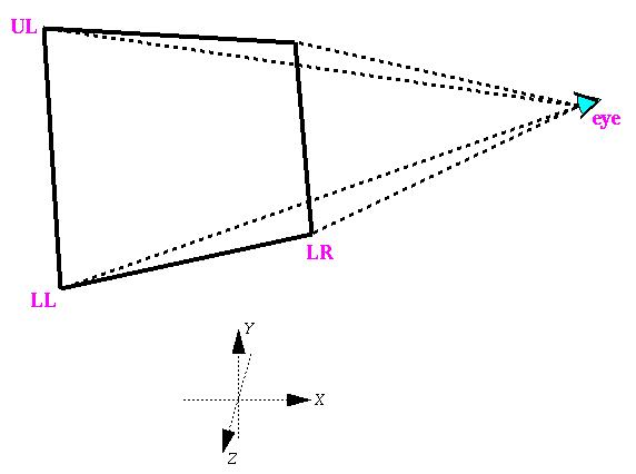
Figure 4. Viewing volume in world coordinate system
The eye point and the edges of the viewing plane (along with near and far clipping distances) define an off-axis frustum for the viewing volume. OpenGL provides a glFrustum() projection function ([6]), which will generate a projection matrix for the case of the eye at the origin, looking down the -Z axis (Figure 5). So, we must simply compute the left, right, bottom, and top distances for the frustum, and a separate viewing matrix which will transform the world from Figure 4 to Figure 5. For simplicity, and generality, we describe a viewing plane to the software by giving the world coordinates of three of its corners - the lower left (LL), upper left (UL), and lower right (LR). The eye position (E) is provided by head tracking routines, and is in the same world coordinate system as the screen corners.
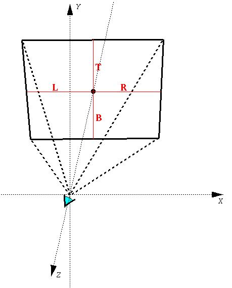
Figure 5. glFrustum() viewing volume
The distance L in the viewing frustum is distance from the left edge of the screen to the projection of the eye point onto the plane of the screen; this is equal to the projection of the vector from the lower left corner to the eye (E - LL) onto the bottom edge of the screen (LR - LL). Similarly, the distance B is equal to the projection of the vector to the eye (E - LL) onto the left edge of the screen (UL - LL). We compute unit vectors for these screen edges, which can be regarded as axes of the screen coordinate system (XS and YS). Then we take an inner product with the eye vector (ES) to obtain the frustum values; it is thus equivalent to finding the eye position in the screen's coordinate system.
LR - LL
XS = ¾ ¾ ¾ ¾ width = || LR - LL ||
width
UL - LL
YS = ¾ ¾ ¾ ¾ height = || UL - LL ||
height
ES = E - LL
L = ES · XS R = width - L
B = ES · YS T = height - B
L, R, B, and T are the distances to the screen edges on the screen plane. The left / right / bottom / top arguments for glFrustum() must be the distances to the edges on the near clipping plane. So, the values above must be scaled by the ratio of the near clipping distance to the eye-screen distance. The eye-screen distance is computed using the normal to the screen - the Z axis of the screen coordinate system.
ZS = XS ´ YS
distance = ES · ZS
left = - L * near / distance
right = R * near / distance
bottom = - B * near / distance
top = T * near / distance
Finally, we compute the viewing matrix, again using the screen coordinate axes and eye position. Since the screen coordinate axes (XS, YS, ZS) are in world space, they define a transformation (of direction vectors) from screen to world space. The inverse of this transformation forms the rotational part of the desired matrix. The remaining translational part is the translation of the eye (in world coordinates) to the origin.
é XS[0] YS[0] ZS[0] 0 ù
MW¬ S = XS[1] YS[1] ZS[1]
0XS[2] YS[2] ZS[2] 0
ë 0 0 0 1 û
Mview = translate(-E) * MW¬ S -1
The above steps define how to calculate a projection for any arbitrary display screen. All of the calculations could be performed at each frame; however, depending on specific details of a device, the procedure can be optimized by saving appropriate results. We break down our generic "screens" into three possible cases - projection screens which remain fixed in world space (such as the CAVE), screens which remain fixed relative to the eye (HMDs), and screens which can move independent of the eye. For fixed, CAVE-like displays, the screen axes (XS, YS, ZS) and the rotational part of the viewing matrix (MW¬ S -1) stay constant and can be saved. For HMDs, the viewing frustum stays constant. For independently moving screens, everything must be recalculated at each frame.
Display Parameters
In addition to computing correct, viewer-center projections for the stereo display, we must deal with how stereo pairs of images are to be displayed. There are a number of different common, and not so common, methods, which can be reduced to a set of OpenGL rendering attributes.
The CAVE and most other projection-based systems use liquid crystal shutter glasses in an active stereo system, where both images of a stereo pair are time multiplexed in a single video signal. On older, or lower-end, workstations, one image is rendered in what is normally the upper half of the graphics screen, and the other image is rendered in the bottom half; a special video format interleaves these two fields so that each covers the full screen (on SGI workstations, this is referred to as "STR_RECT" stereo mode). Newer workstations use quad-buffering, which assigns a completely separate buffer for each image; again, a special workstation video format merges these two buffers into the final video signal.
Some systems, such as the Infinity Wall and Fakespace VersaBench ([7]), use passive, polarized glasses for stereo. In this case, the left and right images are separate video signals. They may be generated by individual graphics pipes of a workstation, or separate video channels from a single graphics pipe, on workstations which support this. Many stereo HMDs are similar, in that they take separate video signals for the left and right eyes' displays.
Less common stereo encoding methods include side-by-side, anaglyphic, and interlaced images. Some models of the BOOM system take a single video signal, where the left and right views appear side by side on the workstation display; the BOOM hardware splits this into the two separate images. "Free-viewing" stereo images may similarly be displayed simply as two images next to each other on a screen. In anaglyphic stereo, one image is drawn only in red, and the other only in green, and they are viewed with glasses with color filters; displaying different images in the red, green, and blue color channels of a video signal may also be used to generate two or more separate monochrome images with a smaller number of video channels. In an NTSC interlaced display, such as the 3DTV shutter glasses system ([8]), images are time multiplexed similar to the "STR_RECT" stereo, but they may also be interlaced in the frame buffer itself. Autostereoscopic, barrier screen systems can also require interlaced images, although in this case vertically rather than horizontally.
Displaying for these different systems requires setting the OpenGL options for window and viewport geometry, left or right stereo buffer, and a color mask. Interlacing can be handled using GL's stenciling feature. In order to make the selections transparent, applications must assume that these options will be taken care of by the rendering framework; application code deals only with the rendering calls to draw objects in the scene. We then provide appropriate settings in a start-up configuration file, and have the framework make the GL calls to select viewport, stereo buffer, color mask, and stencil flag before a given view is rendered. The settings are defined on a per-viewing-channel basis; that is, for each individual eye/screen combination, different settings may be given. In this way, the left and right eye views for a screen may be in a single quad-buffered window, in separate windows on distinct graphics pipes, or some other combination. Multiple screens may also be specified, in any desired combination.
Software Structure
In our implementation of the CAVE software, we provide a basic framework for building VR applications. There are two important aspects of the framework which help make applications portable across display devices. Device-specific information is stored in run-time configuration files, and rendering is handled in a callback structure. The outline of the system is as follows:
read configuration data
for each graphics pipe, start a new process,
open a window, & initialize graphics
in display process:
get current eye position
for each view:
compute perspective
set GL attributes
call application drawing function
synchronize all processes
swap buffers
Because the configuration data, and the actions that depend on them, are hidden from applications, the application code focuses on the manipulation and drawing of the virtual world. The framework automatically takes care of setting up windows, computing and loading the projection transformation, and setting attributes as needed for the stereo display method being used. The framework also handles inter-process synchronization, in order to guarantee that all displays match, both in the eye position that they use, and the time that they swap graphics buffers. In the case of multi-machine systems, this synchronization is normally done using ScramNet reflective shared memory (normal TCP/IP communications can also be used, but they do not provide the same guaranteed, low latency that is important in real-time displays).
In addition to the original, plain GL version of the CAVE software, we have implemented this system using IRIS Performer ([9]). Performer provides tools for real-time, high-performance 3D graphics and manipulation of a virtual world database. The configuration, perspective, and display attribute functions all fit easily into Performer's own framework, in initialization calls and channel callbacks. This maintains the standard Performer programming format, making it straightforward to move existing applications to the CAVE and other systems.
We are presently developing Bamboo modules to provide this same functionality in a still more flexible and extensible system. Bamboo is a portable system for networked virtual environments which focuses on dynamic configuration of applications ([10]). Bamboo applications are composed of dynamically loaded modules; individual modules implement specific functions, and may be combined freely at run-time. The elements under development consist of configuration, display manager, and camera modules. The configuration module determines what sort of system is being used, and dynamically creates and initializes the other modules as needed. The display manager sets up windows and graphics details. The camera computes the stereo projection (using a separate tracker module to get the eye position). A common scene database "attachment point", shared with the display manager, makes it possible for application modules to operate completely independently of the display modules.
Conclusion
We have presented an outline of a system for programming stereoscopic virtual reality displays. The system provides a framework for application development; it automatically handles perspective projection calculations and stereo display options. The projection treats the VR display as one or more arbitrary projection planes, viewed by a tracked user. This model can support a range of devices, from CAVEs to HMDs to newer, experimental systems. The display options provide further flexibility in how stereo images can be displayed. We have used this framework to build a large number of applications, which have been successfully run with a variety of VR devices, without any special changes to the applications.
Acknowledgments
EVL receives major funding from the National Science Foundation (NSF), the Defense Advanced Research Projects Agency, and the US Department of Energy; specifically NSF awards CDA-9303433, CDA-9512272, NCR-9712283, CDA-9720351, and the NSF ASC PACI program. We also acknowledge Silicon Graphics, Inc. and Advanced Network and Services for their support. CAVE and ImmersaDesk are trademarks of the Board of Trustees of the University of Illinois.
References