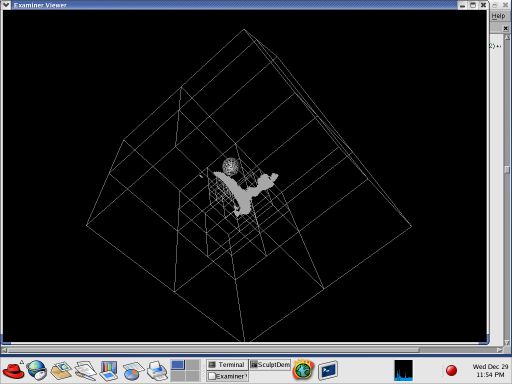
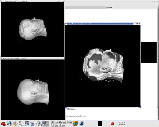
Execution view of SculptDemo
Execution view of SculptDemo
The pipeline
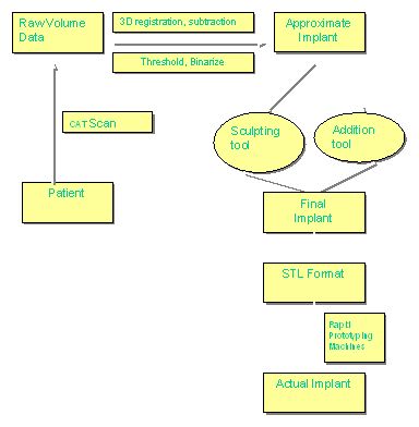
The pipeline
The configuration of the environment is handled through the use of CMake. With the ability to locate separate libraries and paths, CMake makes it very easy to move a project between different platforms. It will generate Makefiles for unix systems and Visual Studio workspaces on Windows. The use of CMake may appear as an extra step, but it provides the flexibility for easily moving between platforms.
CMake can build a project in a different directory than the source code. This capability is useful for keeping source and object files separate. I usually create a 'build' directory within the source code and set CMake to build the project there.
CMake reads the file CMakeLists.txt in the source directory, and that file is used to configure and build the project. This file contains a list of the files and libraries that CMake must find. CMake ships with several modules for finding libraries, but none of them support the libraries used in this project. For this reason, I have written several very simple modules to handle locating required libraries:
These modules will locate the include paths as well as the binary library files. If any are not found, CMake provides a GUI that may be used to manually locate or change the settings. This ability is especially useful with the Inventor module, as a system may have both TGS Inventor and Coin3D installed. The GUI may be used to locate the appropriate library to use.
Running CMakeSetup.exe (Windows) or cmake (unix) will present a GUI. The available settings are displayed, although additional options are available by toggling the Advanced checkbox. Pressing the Configure button will execute the configuration to locate all relevant settings. Once configuration is complete, press Ok to generate the Visual Studio workspace file.
The Visual Studio files (or Makefiles) will be placed in the build directory specified by the user. The .dsw file can be opened to work with the project. CMake creates a BUILD_ALL project that fill the role of the Batch Build command within Visual Studio. It's more convenient than checking multiple project check boxes. To make debugging easier, select SculptDemo and choose 'Set Active Project.'
When it comes time to add files to the project, the proper and portable approach is to create new entries in the CMakeLists.txt file and regenerate the Visual Studio project. Taking these extra steps will make certain that the build process remains portable across multiple system configurations.
The source code is available as a zipped archive. The archive contains all the files but without the CVS directories. Everything should build properly, but contact me if something goes wrong.
 1.4.3
1.4.3